Eye Measurement Apparatus and a Method of Using Same

a technology of eye measurement and eye smear, which is applied in the field of eye measurement apparatus, can solve the problems of subject movement, false indication of misalignment, and difficulty in determining if there is any shift in the alignment imag

Inactive Publication Date: 2009-04-16
BAUSCH & LOMB INC
View PDF31 Cites 45 Cited by
  • Summary
  • Abstract
  • Description
  • Claims
  • Application Information

AI Technical Summary

Problems solved by technology

A drawback of such apparatus is that, while a subject is aligned with the machine before beginning the acquisition of images, a subject may move during acquisition of images for constructing a representation.
In fact, even if eye tracking measurements were attempted after acquisition of the images was begun (i.e., using light from LEDs 152, 154) or light from a slit, since the slit projector, slit camera and the LEDs have been moved (i.e., rotated), it would be difficult to determine if any shift in the alignment images was due to movement resulting from imprecise rotation of the apparatus (e.g., wobble) or due to true misalignment of the patient with the apparatus.
Additional uncertainties would arise because patients' eyes are typically not rotationally symmetric; accordingly, a false indication of misalignment may occur due to projection of the beams on different portions of the eye.

Method used


Image

  • Eye Measurement Apparatus and a Method of Using Same
  • Eye Measurement Apparatus and a Method of Using Same
  • Eye Measurement Apparatus and a Method of Using Same

Examples


Embodiment Construction

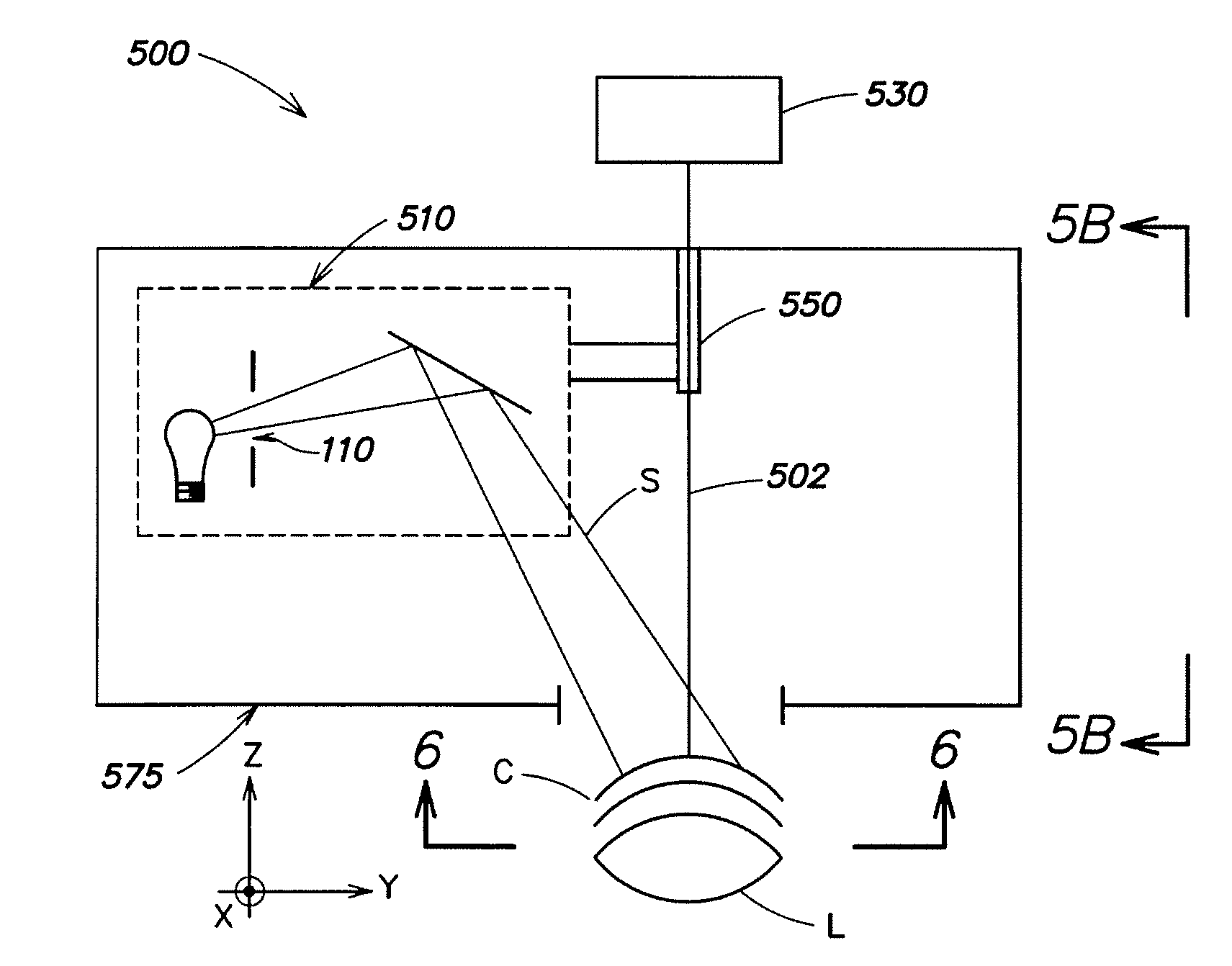
[0021]Aspects of the invention are directed to an apparatus for measuring a subject's eye having an instrument axis. The apparatus comprises 1) an eye tracker apparatus comprising a first projector and a first camera, 2) a slit projector rotatable about the instrument axis independent of the eye tracker apparatus, and 3) a second camera for receiving slit light scattered from the eye, the second camera also being rotatable about the instrument axis independent of the eye tracker apparatus. It will be appreciated that, in use, the eye tracker will typically remain stationary during acquisition of images for a given subject to reduce the uncertainty that arises when the eye tracker is rotated; however, the eye tracker may be translatable or rotatable, for example, to calibrate the apparatus.

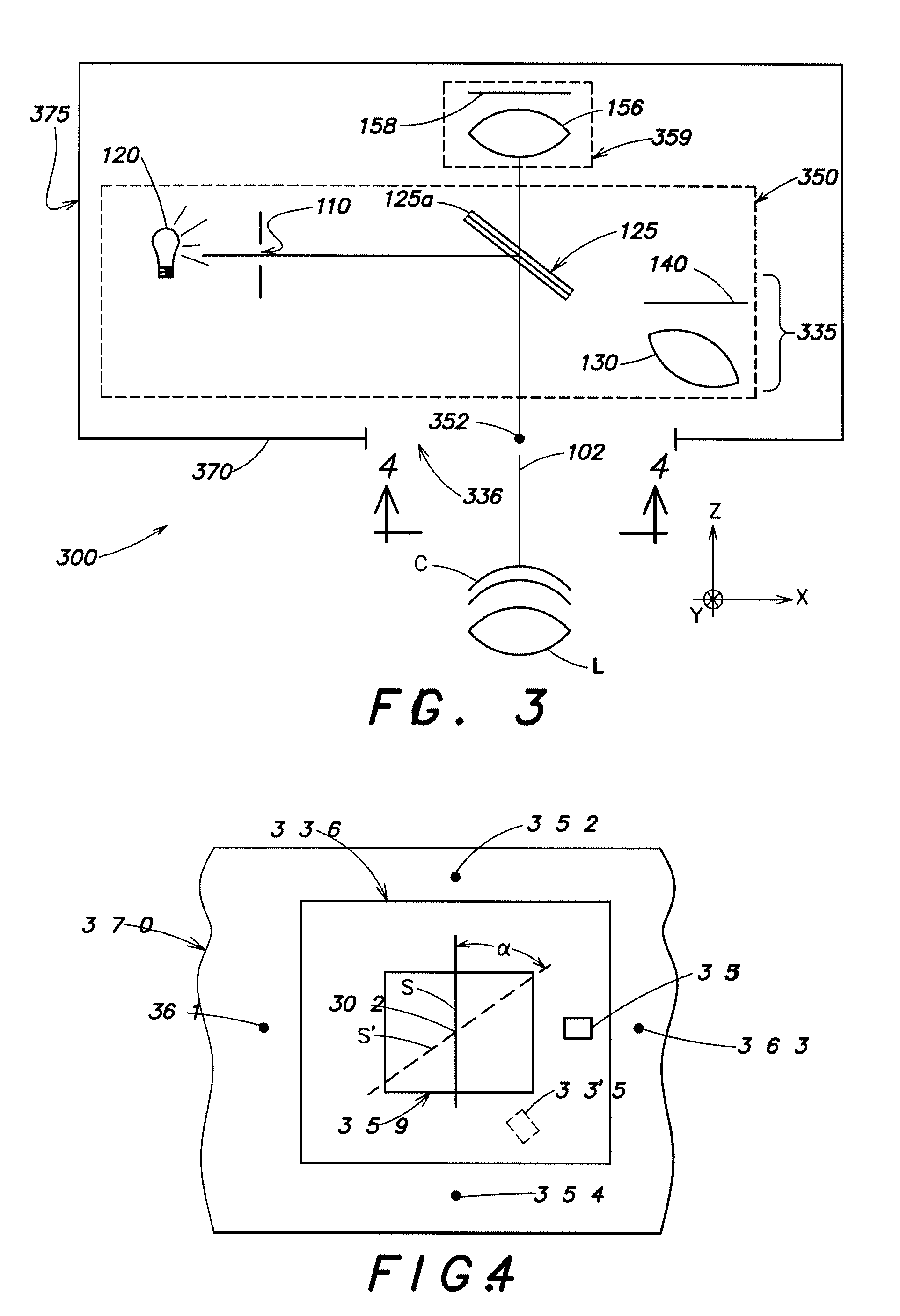
[0022]FIG. 3 is a schematic view of an example of an embodiment of an eye measurement apparatus 300 according to aspects of the present invention illustrating optical layout. For example, the eye m...


PUM


Abstract

An apparatus for measuring a subject's eye having an instrument axis, comprising an eye tracker apparatus comprising a first projector and a first camera, a slit projector rotatable about the instrument axis independent of the eye tracker apparatus, and a second camera rotatable about the instrument axis independent of the eye tracker.

Description

CROSS-REFERENCE[0001]This application claims the benefit of U.S. Provisional Patent Application No. 60 / 978,923 filed Oct. 10, 2007, which is incorporated by reference herein.FIELD OF INVENTION[0002]The present invention relates to eye measurement apparatus and a method of using same, and more particularly to an eye measurement apparatus including an eye tracker and method of using same.BACKGROUND OF THE INVENTION[0003]Ophthalmologists and optometrists would like to have accurate representations of portions of subjects' eyes. Such representations include, for example, representations of a subject's corneal surfaces, corneal thickness, corneal density and lens surfaces. This information may be used, for example, to prescribe contact lenses and eye glasses, and to reshape the cornea by surgical procedures or to perform other surgical procedures. Since it is not comfortable to measure these data by physical contacting an eye, remote sensing techniques are preferably used to obtain the r...

Claims


Application Information

Patent Timeline
Patent Type & Authority Applications(United States)
IPC IPC(8): A61B3/14A61B3/113A61B3/107
CPCA61B3/036A61B3/113A61B3/154A61B3/135A61B3/145A61B3/1173
Inventor LAI, MINGEAGAN, BARRY T.
Owner BAUSCH & LOMB INC
Why Eureka
Try Eureka