
Rotor blade folding system

a rotary-wing aircraft and blade technology, applied in the direction of liquid fuel engines, marine propulsion, vessel construction, etc., can solve the problems of affecting the utility of rotary-wing aircraft, affecting the operation of rotary-wing aircraft in certain environments, and limiting the overall structural envelope of rotary-wing aircra

Active Publication Date: 2009-04-16
SIKORSKY AIRCRAFT CORP
View PDF19 Cites 27 Cited by
  • Summary
  • Abstract
  • Description
  • Claims
  • Application Information

AI Technical Summary

Benefits of technology

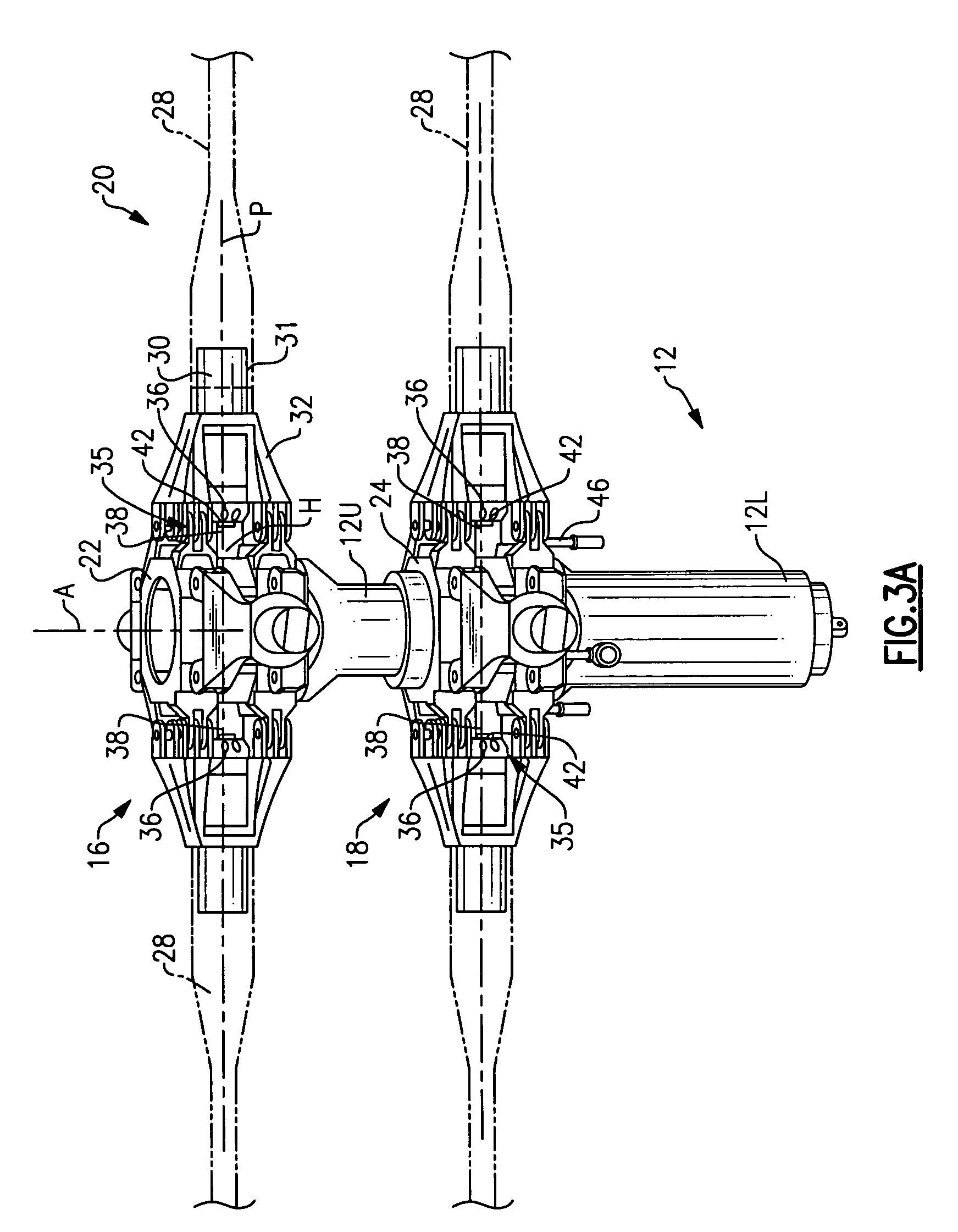
[0011]The rotor blade folding system essentially collapses the rotor hub by locating the fold hinge axis in a position which results in a more compact rotor hub assembly. By folding the entire pitch bearing assembly, pitch lock systems are minimized or eliminated as the pitch lock system need only react a blade-feathering moment which is typically three orders of magnitude less than that required of a conventional blade-fold system. That is, since blade fold occurs inboard of the pitch bearing (semi-rigid or articulated), the 1 G droop moment will not produce a torsion about the pitch bearing degree of freedom, and the pitch lock can be a much smaller structure. Folding the blade inboard of the pitch bearing (on a conventional rotor) would require removing the connection between the pitch link and pitch horn. This design provides a novel approach to disengage the pitch control system from the blade for automatic fold.
[0013]The present invention therefore provides a compact rotor blade folding system which protects the blade retention / pitch bearings within a rotor system with a minimum of support structure.

Problems solved by technology

While the flight capabilities of rotary-wing aircraft makes them effective for a wide variety of missions, operation of rotary-wing aircraft in certain environments may be limited by the overall structural envelopes thereof.
The radial dimensions of rotary-wing aircraft main rotor assemblies results in rotary-wing aircraft having relatively large structural envelopes which may impact their utility in some environments.
Blade fold systems may be a challenge because the blade retention / pitch bearing needs to be isolated from the moments generated by the blade when in the folded position.
Without a robust pitch lock system, the rotor blade will drop to the ground.
Since the bearing is no longer in compression, it cannot carry significant shear load.
Such pitch lock and droop stop systems often require a substantial structure to assure proper operation.
Furthermore, some other rotor systems such as a servo-flap rotor system may further complicate pitch-lock during blade fold because there may be no direct control link to the rotor blades.

Method used


Image

  • Rotor blade folding system
  • Rotor blade folding system
  • Rotor blade folding system

Examples


Embodiment Construction

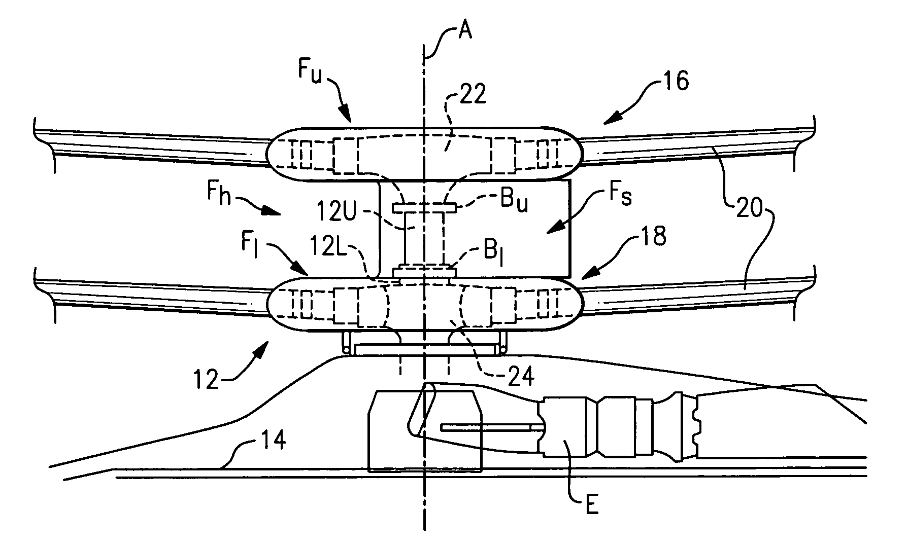
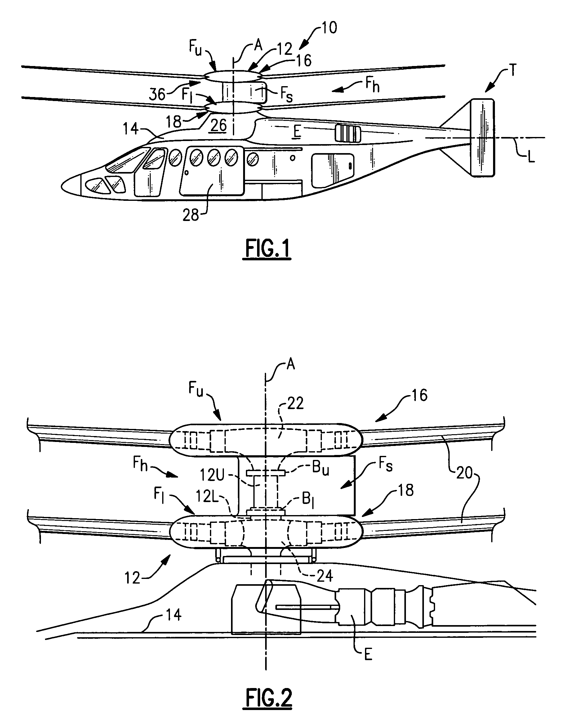
[0025]FIG. 1 illustrates an exemplary vertical takeoff and landing (VTOL) rotary-wing aircraft 10 having a dual, counter-rotating, coaxial rotor system 12 which rotates about an axis of rotation A. The aircraft 10 includes an airframe 14 which supports the dual, counter rotating, coaxial rotor system 12 as well as an optional translational thrust system T which provides translational thrust generally parallel to an aircraft longitudinal axis L. Although a particular aircraft configuration is illustrated in the disclosed embodiment, other counter-rotating, coaxial rotor systems will also benefit from the present invention.

[0026]A main gearbox 26 which may be located above the aircraft cabin drives the rotor system 12. The translational thrust system T may be driven by the same main gearbox 26 which drives the rotor system 12. The main gearbox 26 is driven by one or more engines (illustrated schematically at E). As shown, the main gearbox 26 may be interposed between the gas turbine e...


PUM


Abstract

A rotor blade folding system includes a bearing housing which supports a bearing and rotor blade spindle which folds relative the rotor hub assembly about a fold axis. The rotor blade folding system essentially collapses the rotor hub to facilitate compatibility with a fairing system. By rotating the entire pitch bearing assembly, pitch lock systems are also minimized as the pitch lock system need only react a blade-feathering moment.

Description

BACKGROUND OF THE INVENTION[0001]The present invention relates to a blade fold system for a rotary-wing aircraft, and more particularly to a bearing housing mounted rotor blade bearing assembly which folds relative a rotor hub assembly to minimize pitch lock system requirements.[0002]While the flight capabilities of rotary-wing aircraft makes them effective for a wide variety of missions, operation of rotary-wing aircraft in certain environments may be limited by the overall structural envelopes thereof. The radial dimensions of rotary-wing aircraft main rotor assemblies results in rotary-wing aircraft having relatively large structural envelopes which may impact their utility in some environments.[0003]Rotary-wing aircraft, particularly military rotary-wing aircraft utilized for maritime flight operations, may be required to conduct operations from ships for extended periods of time. Shipboard space is generally at a premium, and the structural envelopes of rotary-wing aircraft may...

Claims


Application Information

Patent Timeline
Patent Type & Authority Applications(United States)
IPC IPC(8): B64C27/50
CPCB64C27/50B64C27/10
Inventor CABRERA, PEDRO L.SCHMALING, DAVID N.
Owner SIKORSKY AIRCRAFT CORP
Learn More