Apparatus and method for ultrasound treatment

Inactive Publication Date: 2009-04-16
ULTRASHAPE INC
View PDF5 Cites 51 Cited by
  • Summary
  • Abstract
  • Description
  • Claims
  • Application Information

AI Technical Summary

Benefits of technology

[0019]An aspect of some embodiments of the invention relates to providing relatively simple methods of providing

Problems solved by technology

However, it is often difficult to control high energy focused ultrasound to satisfy constraints that may be required to perform various procedures for which it is intended.
For example, HIFU beams are often focused to a relatively small volume of tissue and can require a relatively large dwell time at the focal volume to destroy tissue therein.
Treating an extended region of tissue with HI

Method used


Image

  • Apparatus and method for ultrasound treatment
  • Apparatus and method for ultrasound treatment
  • Apparatus and method for ultrasound treatment

Examples


Embodiment Construction

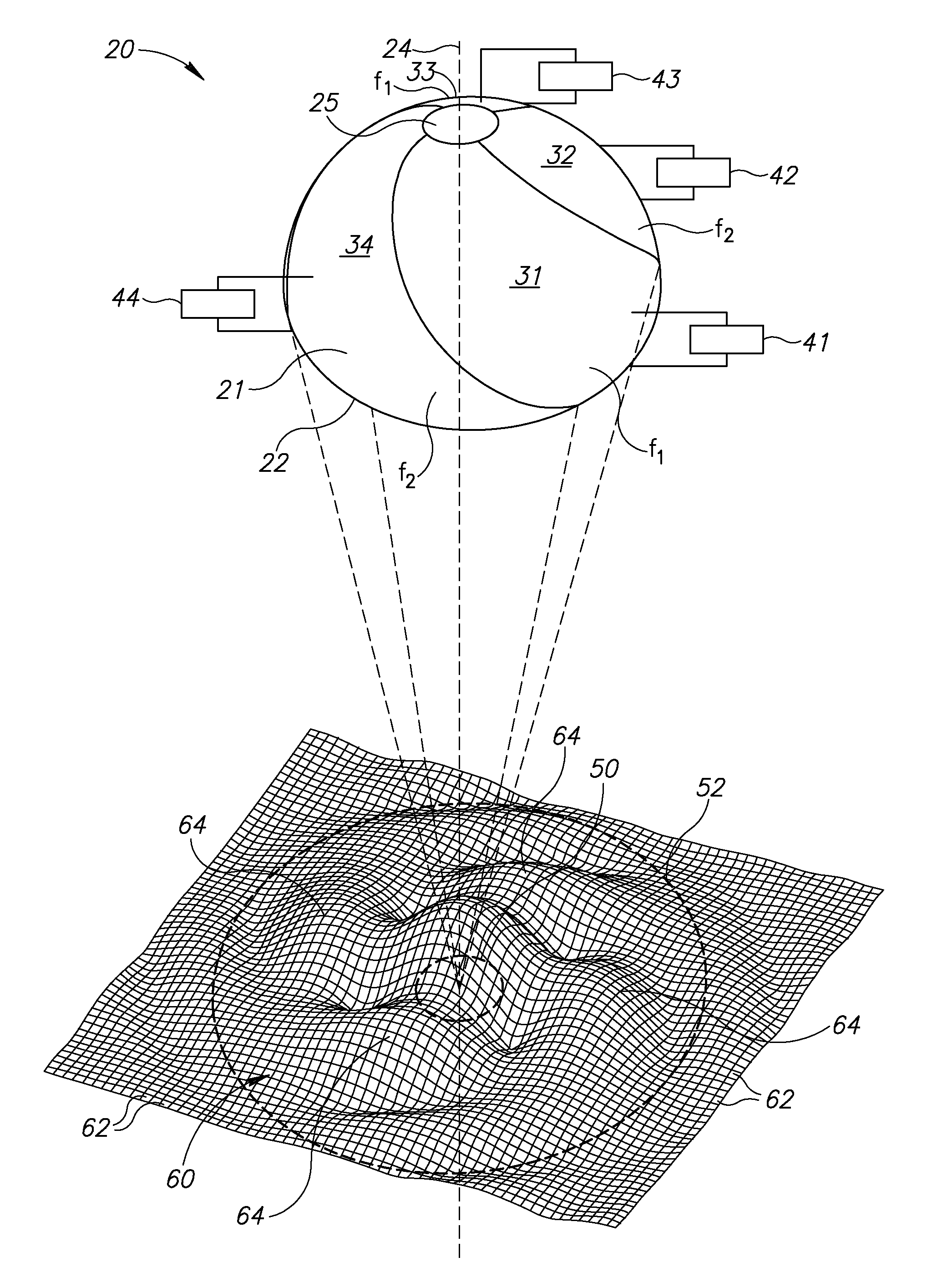
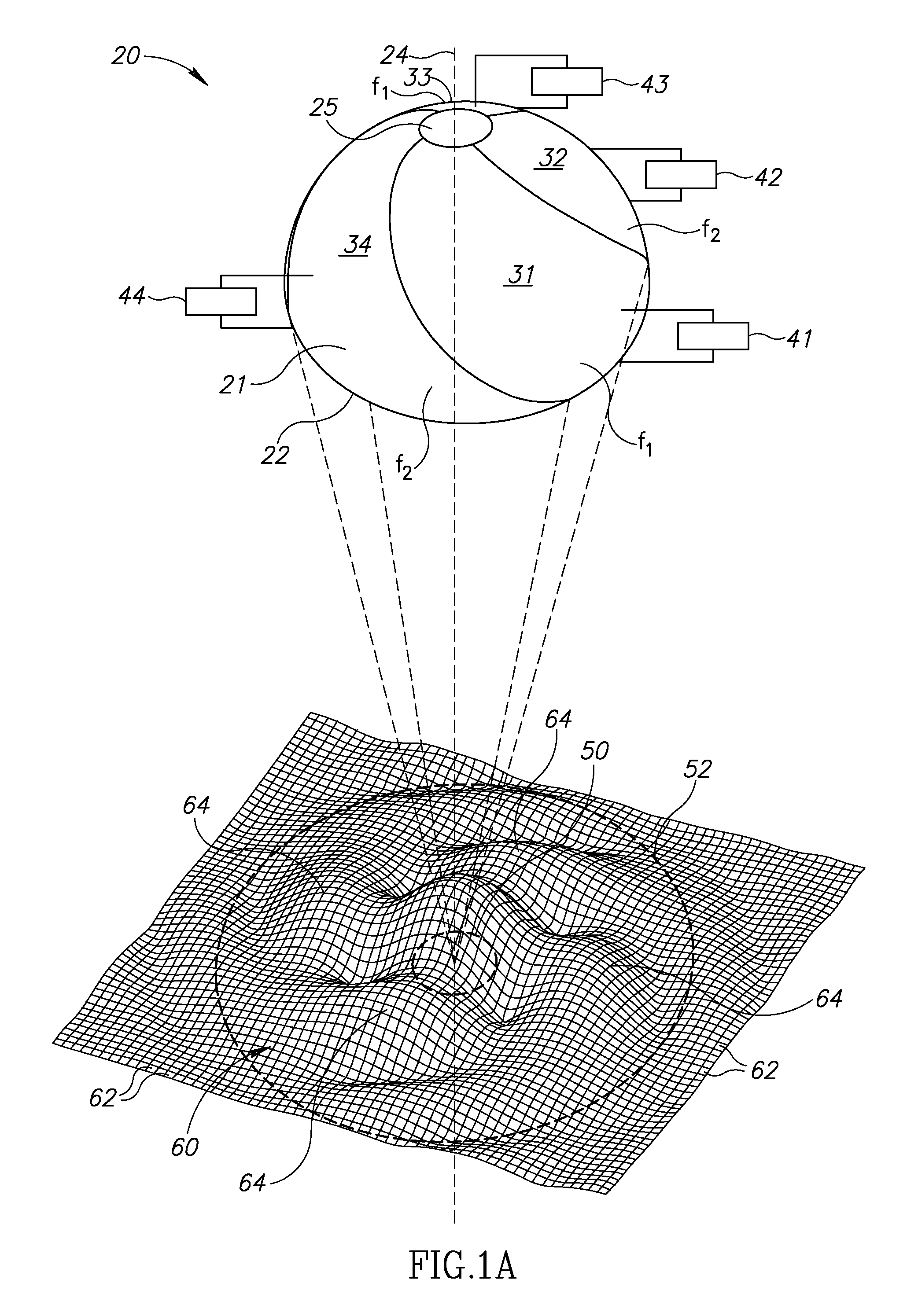
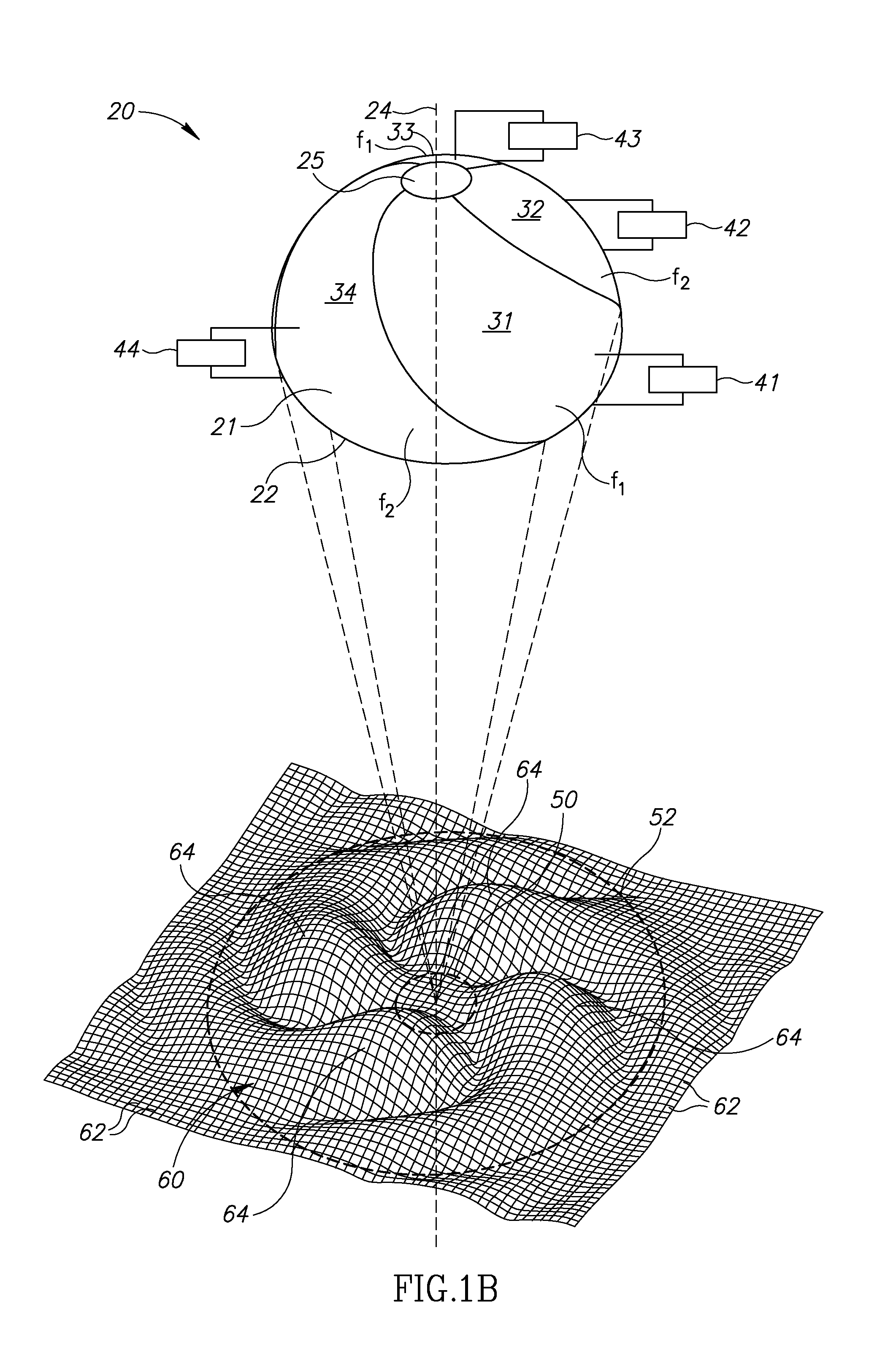
[0034]FIGS. 1A-1D schematically show perspective views of a multielement spherical cap transducer 20 having convex and concave sides 21 and 22 and comprising a plurality of, optionally, four crescent shaped sector piezoelectric elements 31, 32, 33, 34, in accordance with an embodiment of the invention. Each crescent sector element 31-34, has a first electrode (not shown) substantially covering a top surface of the sector on convex side 21 of cap transducer 20 and a second electrode substantially covering concave side 22 of the cap transducer. Crescent sector elements 31, 32, 33 and 34 are optionally connected to power supplies 41, 42, 43 and 44 respectively that are controllable to excite the crescent sector elements to radiate acoustic energy. Cap transducer 20 has an axis 24 and is formed having a hole 25 centered on the axis for convenience of production and to provide a convenient location for a sensor, optionally an acoustic sensor, for monitoring an acoustic field generated by...


PUM


Abstract

A transducer for generating an intensity pattern of ultrasound comprising: a plurality of elements independently excitable to radiate acoustic energy; and a controller that simultaneously excites some of the elements while leaving at least one element dormant and changes which element is dormant to change the intensity pattern.

Description

FIELD[0001]The invention relates to methods and apparatus for performing acoustic procedures on tissue.BACKGROUND[0002]Various methods are known for delivering and coupling acoustic energy to a region of tissue to perform a diagnostic and / or therapeutic and / or cosmetic procedure on a patient's tissue. Among such procedures are for example, non-invasive assaying of blood analytes, drug delivery by phonophoresis, lithotripsy, tissue ablation and lysis of fat cells for cosmetic removal of adipose tissue.[0003]For many types of therapeutic and / or cosmetic acoustic applications, such as for example lithotripsy, tissue ablation and lysis noted above, sufficient acoustic energy must be delivered to a tissue region to destroy and remove tissue in the region. Generally, the acoustic energy is delivered by focusing at least one beam of relatively intense ultrasound on the region. The high intensity, focused ultrasound, conventionally referred to by the acronym “HIFU”, may be used to generate ...

Claims


Application Information

Patent Timeline
IPC IPC(8): A61H1/00
CPCA61H23/0236A61N7/00A61N2007/0008G10K11/345A61N2007/0073A61N2007/0078A61N2007/0095A61N2007/0065
Inventor RYBYANETS, ANDREY
Owner ULTRASHAPE INC
Why Eureka
Try Eureka