
Method and machine for converting heat to power

a technology of heat and power, applied in the direction of machines/engines, reciprocating piston engines, positive displacement engines, etc., can solve the problems of requiring fuel which is very expensive to create heat, and reducing the heat generation efficiency of combustion, so as to reduce the temperature of the heat source liquid, reduce the cost of pistons and cylinders, and reduce the effect of vapor pressur

Inactive Publication Date: 2009-04-23
DINH HUY HAI +2
View PDF5 Cites 0 Cited by
  • Summary
  • Abstract
  • Description
  • Claims
  • Application Information

AI Technical Summary

Benefits of technology

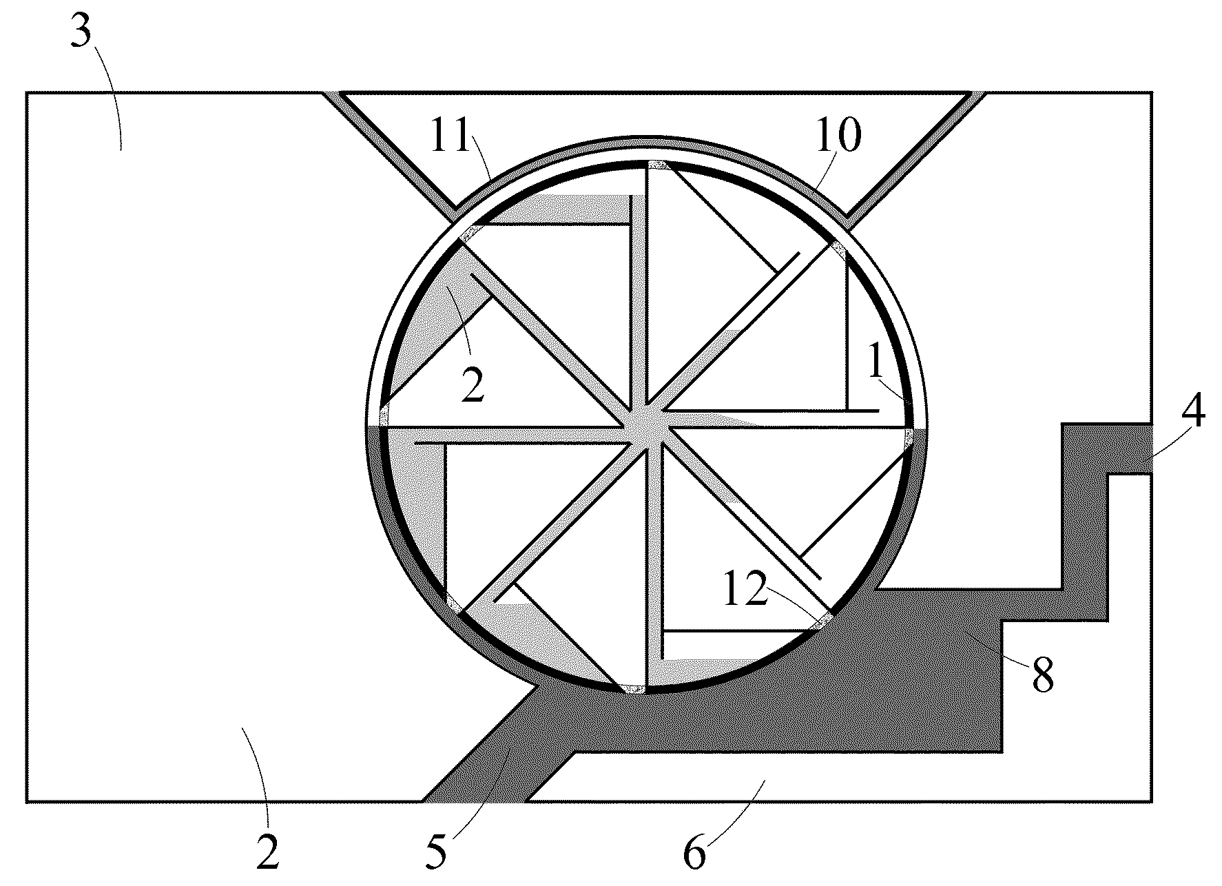
[0003]The present invention overcomes above three drawbacks. First, the invention uses heat from any source such as air, water, and sunlight. Second, the invention recycles the working vapor to preserve the heat in the working vapor. Third, the invention works at considerably low temperature and pressure; hence, it eliminates expensive pistons and cylinders. A heat machine is powered by any kind of heat source liquid. The core part of a heat power machine is a special closed cylinder. As a heat source liquid passes through the lower left side of the cylinder, heat is transferred from the heat source liquid to the working liquid and vapor in the lower left side of the cylinder. As the result, the temperature of the heat source liquid is lowered. As heat is transferred to the working liquid on the left side, the working liquid is boiled to vapor and its vapor pressure is increase. Therefore, the remaining working liquid is pushed to the right side. The high pressure in the working liquid presses the vapor on the right back to working liquid. The buoyant force on the left and the gravitational force on the right make the cylinder rotate counterclockwise to produce power. A heat isolating enclosure ensures that heat is not transferred to or from the right side of the cylinder.

Problems solved by technology

First, it requires fuel which is very expensive to create heat.
Second, because it dumps the working vapor after producing power, most of the heat created from burning is lost.
Third, because pistons and cylinders have to bear high temperature and pressure, it is expensive to make.

Method used


Image

  • Method and machine for converting heat to power
  • Method and machine for converting heat to power
  • Method and machine for converting heat to power

Examples


Embodiment Construction

[0012]The present invention now will be described more fully hereinafter with reference to the accompanying drawings, in which one example of the embodiments of the invention are shown. Indeed, the invention may be embodied in many different forms and should not be construed as limited to the embodiment set forth herein; rather, the embodiment is provided by way of example so that this disclosure will satisfy applicable legal requirements.

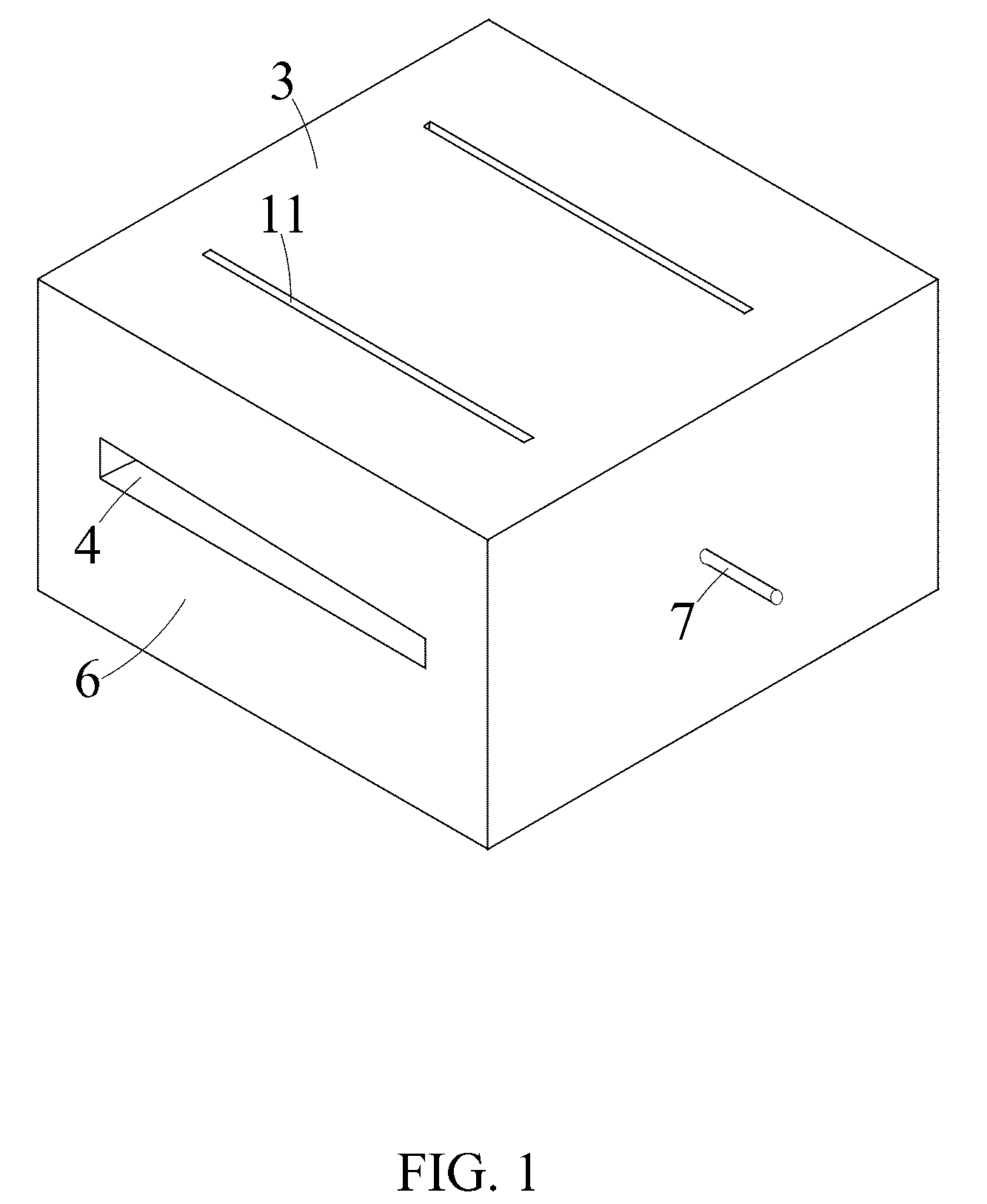
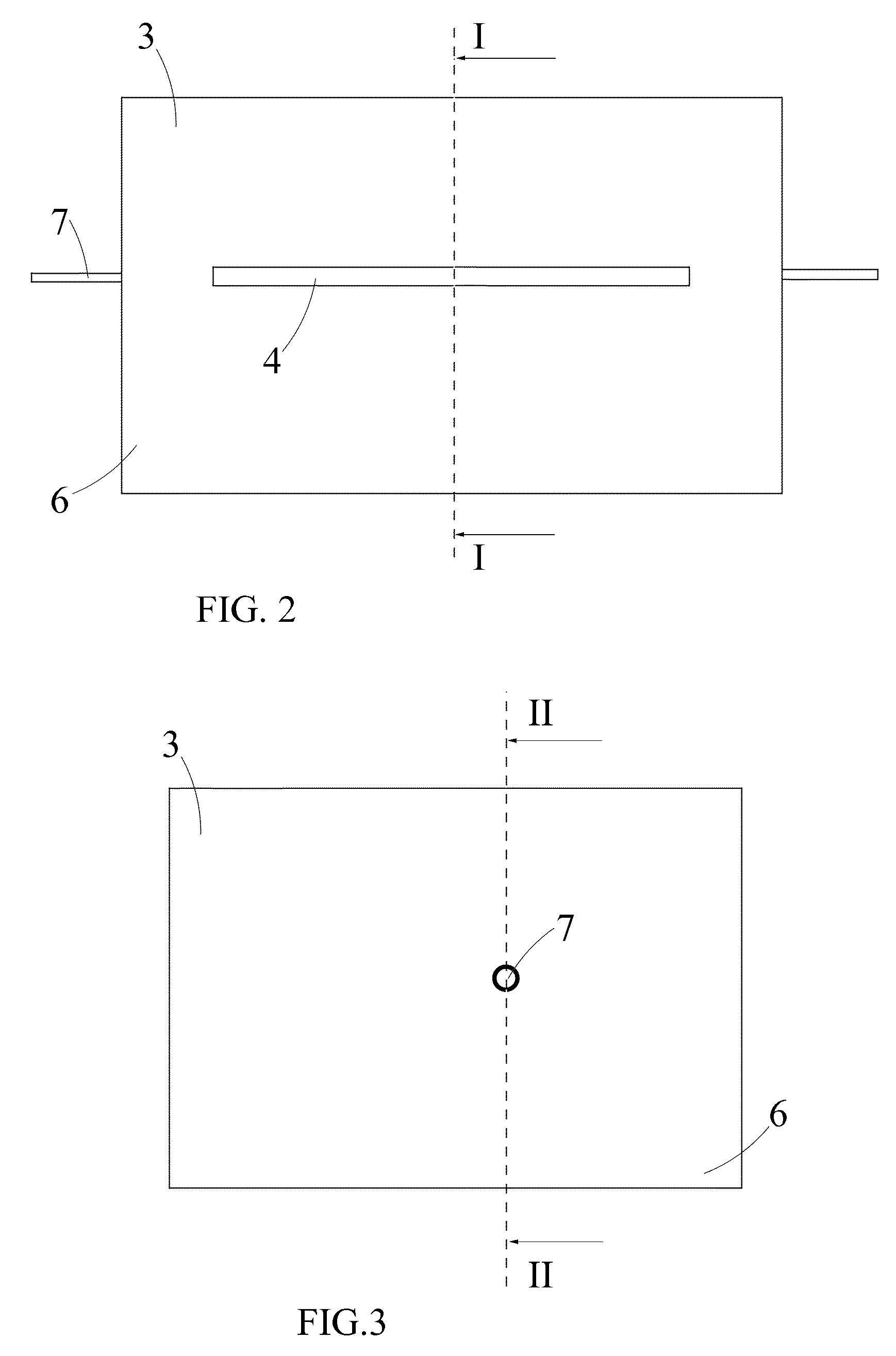
[0013]FIG. 6 illustrates the cross sectional view of the machine at the middle and perpendicular to the axis of the cylinder (1) as shown in FIG. 2 when the machine is working. A heat power machine is made up of a closed hollow cylinder (1). The side of the cylinder (1) is made of high heat conducting material. The bottom and the top (9) of the cylinder (1) are made of a heat isolating material. The cylinder (1) can rotate around its axis by two shafts (7) that are attached to center of the bottom and the top (9). The side of the cylinder (1) is di...


PUM


Abstract

A method is invented for converting heat in a liquid to power and generating thermal difference of the heat source liquid between the inlet and the outlet of a machine. The heat source liquid (8) is drawn to the lower right side of the cylinder (1) through the inlet (5). The heat in the heat source liquid (8) boils the working liquid (2) at the right side of the cylinder (1). The vapor from the boiling creates pressure to push working liquid (2) to the left of the cylinder (1) and to compress the vapor at the left side back to working liquid. The buoyant force on the right and the gravitational force on the left of the cylinder (1) rotate the cylinder (1) to produce power. As heat is transferring to the cylinder (1), the temperature of the heat source liquid (8) is lower at the outlet (4).

Description

FIELD OF THE INVENTION[0001]The present invention relates to a method for converting heat to power.BACKGROUND[0002]Present day machines usually burn fuel, then transfer the heat from burning to working vapor to create high pressure vapor. Then this high pressure vapor pushes a piston in a cylinder to produce power. After that, the working vapor is dumped to the outside environment. This method of producing power has three big drawbacks. First, it requires fuel which is very expensive to create heat. Second, because it dumps the working vapor after producing power, most of the heat created from burning is lost. Third, because pistons and cylinders have to bear high temperature and pressure, it is expensive to make.SUMMARY OF THE INVENTION[0003]The present invention overcomes above three drawbacks. First, the invention uses heat from any source such as air, water, and sunlight. Second, the invention recycles the working vapor to preserve the heat in the working vapor. Third, the inven...

Claims


Application Information

Patent Timeline
Patent Type & Authority Applications(United States)
IPC IPC(8): F03C5/00F03C99/00
CPCF03G7/06
Inventor DINH, HUY HAIBUI, PHI NGUYETDINH, ANHQUAN HOANG
Owner DINH HUY HAI
Learn More