
Moulding device

a moulding device and moulding technology, applied in the direction of ceramic shaping apparatus, coatings, instruments, etc., to achieve the effect of convenient inserting

Inactive Publication Date: 2009-04-23
FORCE TECH
View PDF7 Cites 2 Cited by
  • Summary
  • Abstract
  • Description
  • Claims
  • Application Information

AI Technical Summary

Benefits of technology

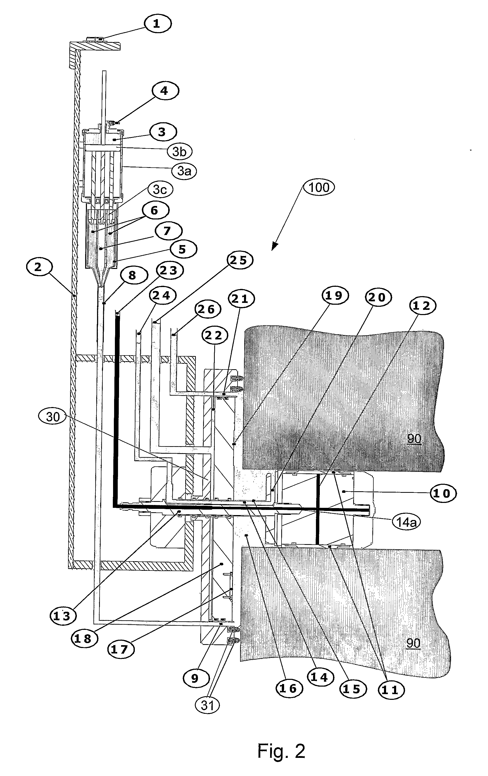
[0017]According to an advantageous embodiment, the moulding device according the invention moreover comprises means for reducing the volume of the moulding chamber formed. When the volume of the moulding device can be reduced, the moulding chamber can be filled up substantially completely with moulding material, and this moulding material can subsequently be put under increased pressure by said volume reduction. Typically, the area of the first moulding chamber part is magnitudes greater than the cross-sectional area of the at least one outlet; this ensures that the movement of the movable plate results in an increased pressure inside the moulding chamber. Hereby, any small occurrences of fluid within the moulding material can be removed, i.e. forced out by the increased pressure. This results in a considerably enhanced quality of the cast and surface imprint thereof. It should be noted, that the movable plate can have any appropriate shape adapted to the surface and the shape and size of the moulding chamber. Thus, it could be curved, flat or shaped to correspond to a specific geometry.
[0020]According to yet another embodiment of the invention, the first moulding chamber part or the movable plate moreover comprises a test piece with surface defects having well-known characteristics. This test piece is placed at the surface of first moulding chamber part or at the movable plate, if this is present in the moulding chamber, so that the surface of the cast resulting from the moulding which has been adjacent to the test piece (i.e. either the first moulding chamber part or the movable plate) comprises an imprint of the test piece. Thus, if the test piece is known to have a characteristic of a predetermined size, such as 1 μm, the presence or absence of an imprint of this characteristic indicates whether the quality of the cast has been adequate to detect flaws / defects of this predetermined size. Thus, a reliable quality control is achieved.
[0022]According to an embodiment of the invention, the moulding device moreover comprises an axle connecting the first moulding chamber part to the second moulding chamber part. Thus, the first and second moulding chamber part can be moved as one coherent part. Moreover, the second moulding chamber part adapted to be inserted into the passage in the surface, can be adapted for fixating the moulding device to the surface to be inspected. Hereby, the second moulding chamber part has two functions: to delimit the moulding chamber together with the first moulding chamber part and the surface and to assist in fixating the moulding device to the surface.
[0023]According to yet another embodiment, the axle comprises a first channel with two ends, whereof one end is arranged to be an outlet for letting fluid from the moulding chamber into the channel and whereof the other end is arranged to be an outlet for letting out fluid from the channel. Hereby, it is possible to provide an outlet close to the upper part of the indentation formed by the passageway, close to the second moulding chamber part, thereby facilitating the escape of fluid from the indentation.
[0024]Advantageously, the second moulding part is an expandable member, and the axle moreover comprises a second channel with two ends, whereof one end is arranged to be an inlet of pressurized fluid and the other end is an outlet into the inside of the expandable member. Hereby, the second moulding part arranged to be inserted into the passage in the surface can have a size and shape adapted to the size and shape of the passage, so that it can easily be inserted therein. After the insertion, pressurized fluid, e.g. pressurized water, can be let into the second channel to make the expandable member expand to seal towards the passage in the surface. Hereby, the second moulding chamber part is fixated inside the passage and seals off the moulding chamber. The expandable member can be any appropriate member, for example an expandable rubber plug.
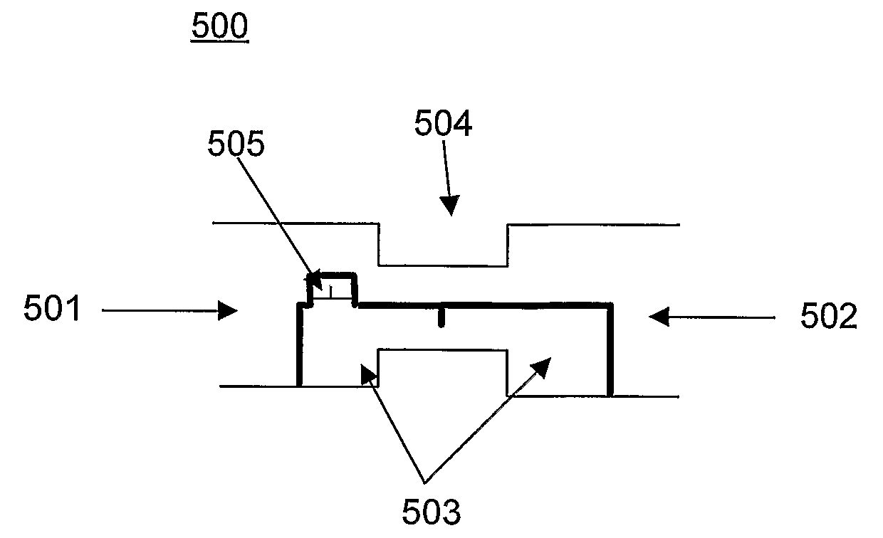
[0032]at least one test piece with surface defects having well-known characteristics for making at least one imprint on said cast of said surface.Thereby the moulding device may delimit a section of a surface comprising for example a length of a pipe with a reduced diameter e.g. a reducer section of a pipe. Further, the moulding device may inject moulding mass from both moulding devices / sections and / or the moulding device may reduce the volume of the mould using both devices / sections.

Problems solved by technology

Further, the moulding device comprises at least one test piece with surface defects having well-known characteristics for making at least one imprint on said cast of said surface.

Method used


Image

  • Moulding device
  • Moulding device
  • Moulding device

Examples


Embodiment Construction

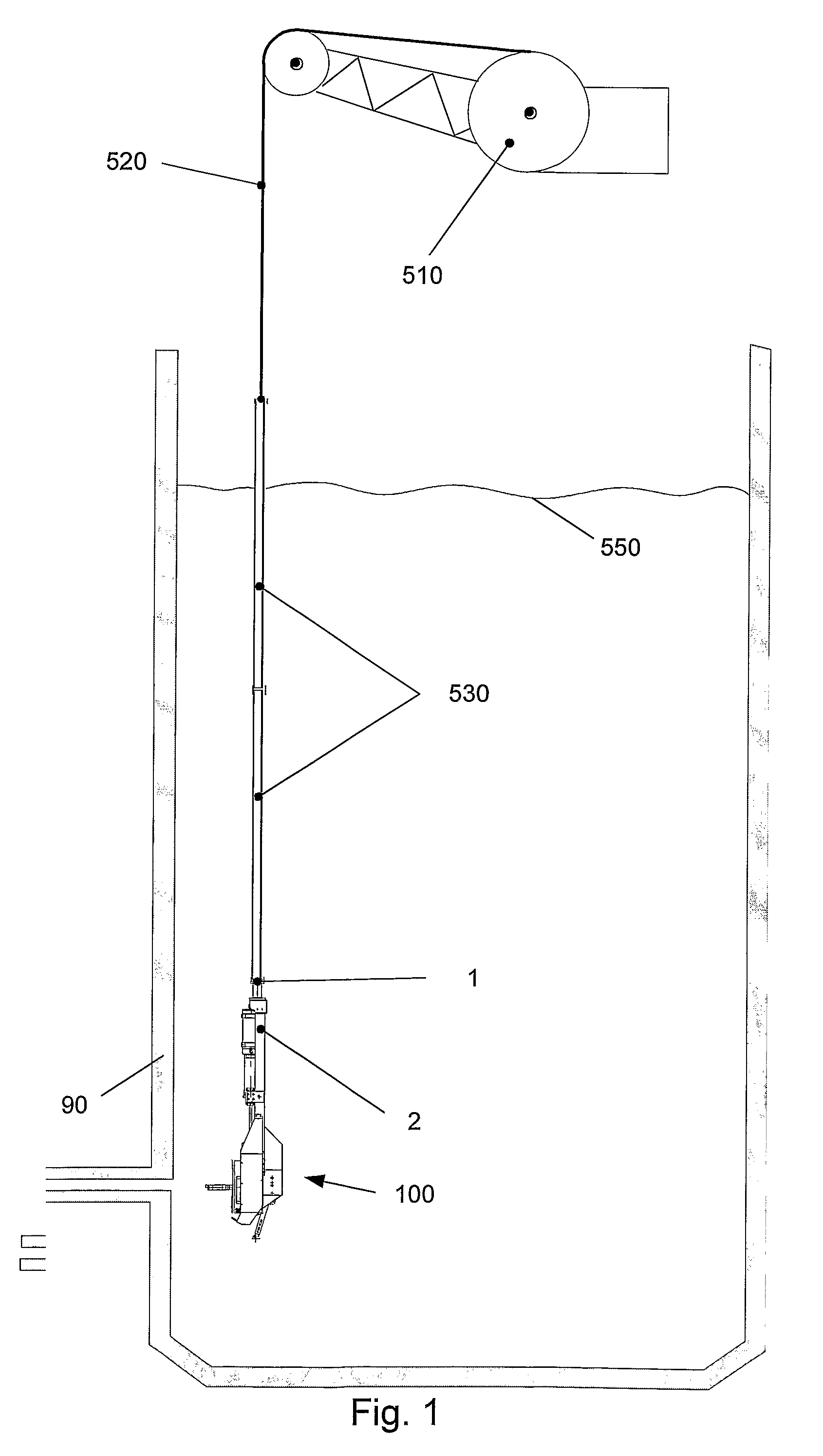
[0040]FIG. 1 is a schematic drawing of a moulding device 100 and placing means 510, 520, 530 arranged to place the moulding device 100 adjacent to the surface of a component 90, such as a receptacle.

[0041]The moulding device 100 comprises a frame body 2 (see also FIG. 2) having a fixture 1 arranged to be fixed to placing means 530. The placing means shown in FIG. 1 comprise one or more rods 530, whereof the lower end (of the lower rod 530) is attached to the fixture 1 of the moulding device 100. The placing means shown in FIG. 1 moreover comprises a wire 520 and a crane 510 arranged to wind out / in the wire 520 to thereby lower / raise the rod(s) 530 and any device 100 fixed thereto. Typically, the placing means 510, 520, 530 are separate from the moulding device, e.g. present on-site.

[0042]The placing means 510, 520, 530 should be adapted to be fully remotely controlled and to submerge below a liquid surface 550 to any distance, for example up to 1000 meters.

[0043]The placing means 51...


PUM

PropertyMeasurementUnit
sizeaaaaaaaaaa
distanceaaaaaaaaaa
diameteraaaaaaaaaa

Abstract

This invention is related to a method and a moulding device (100) for making a cast of a surface. The moulding device comprises a first moulding chamber part (30), which is adapted to be placed adjacent the surface and to form a moulding chamber (16) together with the surface. Moulding material can be introduced into the moulding chamber via an inlet (9), and one or more outlets (20, 21) serves to drain the moulding chamber from any entrapped liquid or gas. Further, at least one test piece (17) with surface defects, having well-known characteristics is provided in the moulding device for making at least one imprint on said cast surface. Hereby, a quality test of said cast can be performed.

Description

FIELD OF THE INVENTION[0001]The invention relates to a moulding device for making a cast of a surface, the moulding device comprising a first moulding chamber part adapted to seal off a predetermined part of the surface, fixation means for fixating said first moulding chamber part to the surface so that said first moulding chamber part together with the surface forms a moulding chamber, and an inlet allowing the introduction of moulding material into said moulding chamber. The invention moreover relates to a method of making a cast of at least part of a surface.BACKGROUND OF THE INVENTION[0002]If a surface is hardly accessible, e.g. due to the geometry or location thereof or due to radioactivity, inspection of the surface typically is performed by use of specialized equipment. Tools for remote inspection of a surface by making a cast thereof for later visual analysis of the cast are well-known in the art as described below.[0003]EP 0 337 700 A2 describes an apparatus for inspecting ...

Claims


Application Information

Patent Timeline
Patent Type & Authority Applications(United States)
IPC IPC(8): B28B1/14B29C39/04
CPCG01N1/2806B29C39/026
Inventor HANSEN, PEDER BENTANDREASEN, LARS BODALHOFF, FINNEGENFELDT, SVENDOLSEN, HANS-OLE
Owner FORCE TECH
Learn More