In-vehicle device and vehicular combined control system

Active Publication Date: 2009-04-23
DENSO CORP
View PDF11 Cites 24 Cited by
  • Summary
  • Abstract
  • Description
  • Claims
  • Application Information

AI Technical Summary

Benefits of technology

[0014]It is therefore an object of the present invention to provide an in-vehicle device for a vehicular combined control system which is capable of appropriately controlling both of a function of a smart entry system and a function of a tire pressure monitoring system, and the vehicular combined control system having the in-vehicle device.
[0015]According to one aspect of the present invention, an in-vehicle device for a vehicular combined control system is configured to perform functions of a smart entry system and a tire pressure monitoring system. In the smart entry system, the in-vehicle device conducts radio communication with a portable device carried by a user of a vehicle to conduct authentication required to permit execution of predetermined controls in the vehicle. In the tire pressure monitoring system, the in-vehicle device conducts radio communication with tire pressure sensors thereby to acquire information related to the conditions of the tires. The in-vehicle device is con

Problems solved by technology

However, if the combined system is constructed to include the smart entry system and the TPMS, the combined system does not function as a smart entry system when the ignition is ON unlike the RKE system.
For this reason, as disclosed in U.S. Pat. No. 7,026,953, when the in-vehicle d

Method used


Image

  • In-vehicle device and vehicular combined control system
  • In-vehicle device and vehicular combined control system
  • In-vehicle device and vehicular combined control system

Examples


Embodiment Construction

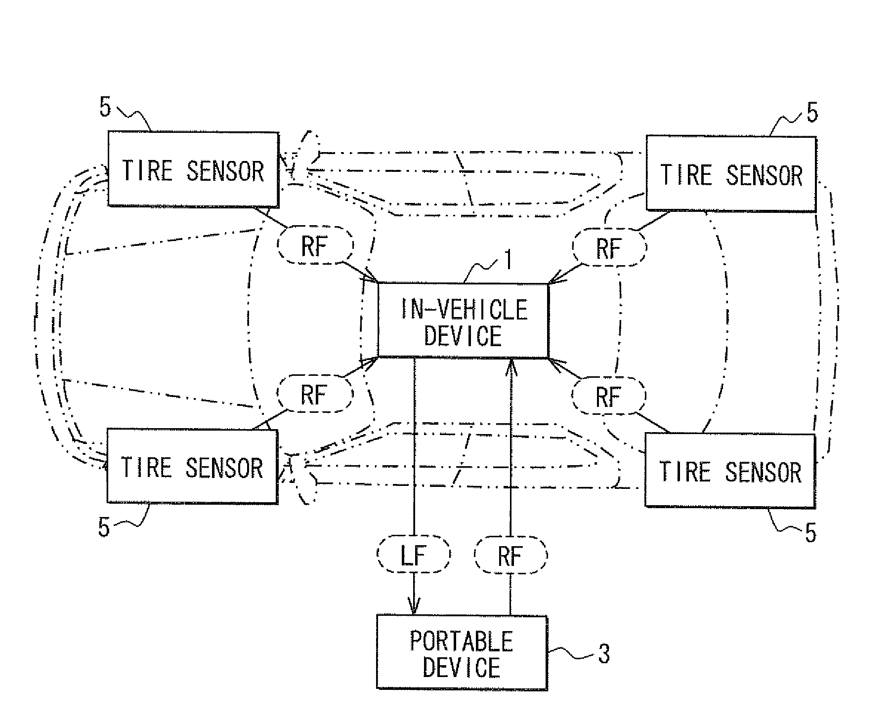
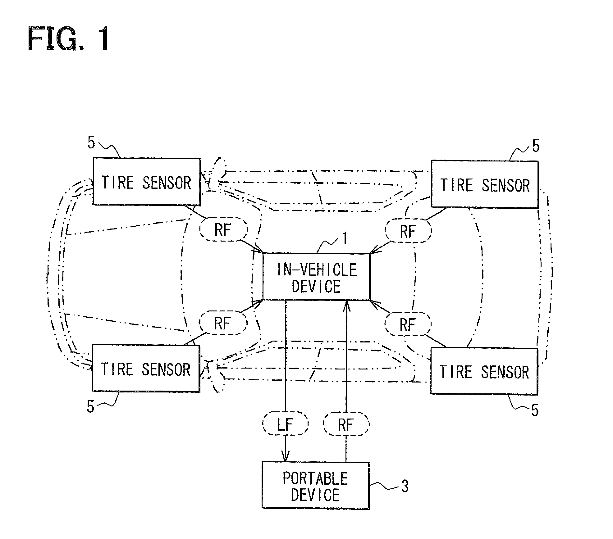
[0022]Referring first to FIG. 1, a vehicular combined control system includes an in-vehicle device 1 that is disposed in a vehicle, a portable device 3 that is carried by a user of the vehicle, tire sensors 5 that are incorporated into interiors of tires which are equipped in front / rear and right / left wheels of the vehicle as detecting means.

[0023]The in-vehicle device 1 is configured to control both of the function of a smart entry system and the function of a tire pressure monitoring system (TPMS).

[0024]The smart entry system conducts authentication by radio communication between the in-vehicle device 1 and a specific portable device 3 that is carried by an authorized user of the vehicle when the portable device 3 enters a radio communication area around the vehicle. When the authentication is approved, the smart entry system executes such a control that the unlock operation of locked vehicle doors or an engine start by the user is permitted. In the smart entry system, the in-vehi...


PUM


Abstract

A vehicular combined control system has functions of a smart entry system and a TPMS. A smart ECU turns on the output of a voltage signal terminal intermittently or in response to a given trigger. When the output of the voltage signal terminal turns on, a RF receiver section receives information from a portable device regardless of the ON/OFF state of an ignition switch to transmit the information to the smart ECU. When the ignition switch is ON and the output of the voltage signal terminal turns off, the RF receiver section receives information from tire sensors to transmit the information to a TPMS microcomputer.

Description

CROSS REFERENCE TO RELATED APPLICATION[0001]This application is based on and incorporates herein by reference Japanese Patent Application No. 2007-271492 filed on Oct. 18, 2007.FIELD OF THE INVENTION[0002]The present invention relates to an in-vehicle device for a vehicular combined control system having the function of a smart entry system and the function of a tire pressure monitoring system, and the vehicular combined control system having the in-vehicle device.BACKGROUND OF THE INVENTION[0003]In many vehicles, an in-vehicle device is mounted to conduct information transmission through a wireless communication with respect to another device to execute various controls.[0004]As one of typical examples, a smart entry system is provided. This system includes an in-vehicle device that is mounted in the vehicle, and a portable device (mobile device) that is carried by a user of the vehicle. The smart entry system is so structured as to execute the control of the locking / unlocking oper...

Claims


Application Information

Patent Timeline
IPC IPC(8): B60C23/02B60C23/04B60R25/01B60R25/10B60R25/24B60R25/34B60R25/40E05B49/00H04B1/16
CPCB60C23/0408B60C23/0435B60C23/0433
Inventor OKADA, NORIAKISUGIURA, MASAHIRO
Owner DENSO CORP
Why Eureka
Try Eureka