Holographic projection method and holographic projection device

a projection device and holographic technology, applied in the field of holographic projection method and holographic projection device, can solve the problems of increasing the illumination optical system, increasing the manufacturing cost, and complicated illumination optical system

Inactive Publication Date: 2009-04-23
OLYMPUS CORP
View PDF17 Cites 36 Cited by
  • Summary
  • Abstract
  • Description
  • Claims
  • Application Information

AI Technical Summary

Benefits of technology

[0029]wherein, in the Fourier transformation step, the Fourier transformation is performed after adding random phases to overlap the video image data. As a result, it is possible to improve diffraction efficiency by using a spatial light phase modulator as an element that displays information subjected to Fourier transformation.
[0104]a projection step of projecting diffraction light, which is irradiated by the light sources and modulated as the spatial phase information by the information display unit, onto projection surfaces. As a result, it is possible to provide a clear video image having no speckle noise.

Problems solved by technology

Therefore, as the light source, a complicated illumination optical system that efficiently and uniformly illuminates light to the image display elements is needed.
As a result, the size of the illumination optical system is increased, which results in increasing manufacturing costs.
As a result, the size of the projection lens is increased, which results in increasing manufacturing costs.
Accordingly, the size of the projection device and the manufacturing costs may be increased.

Method used


Image

  • Holographic projection method and holographic projection device
  • Holographic projection method and holographic projection device
  • Holographic projection method and holographic projection device

Examples


first embodiment

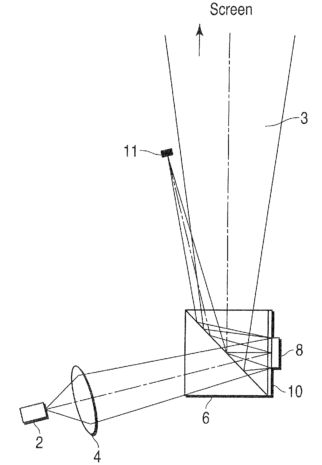
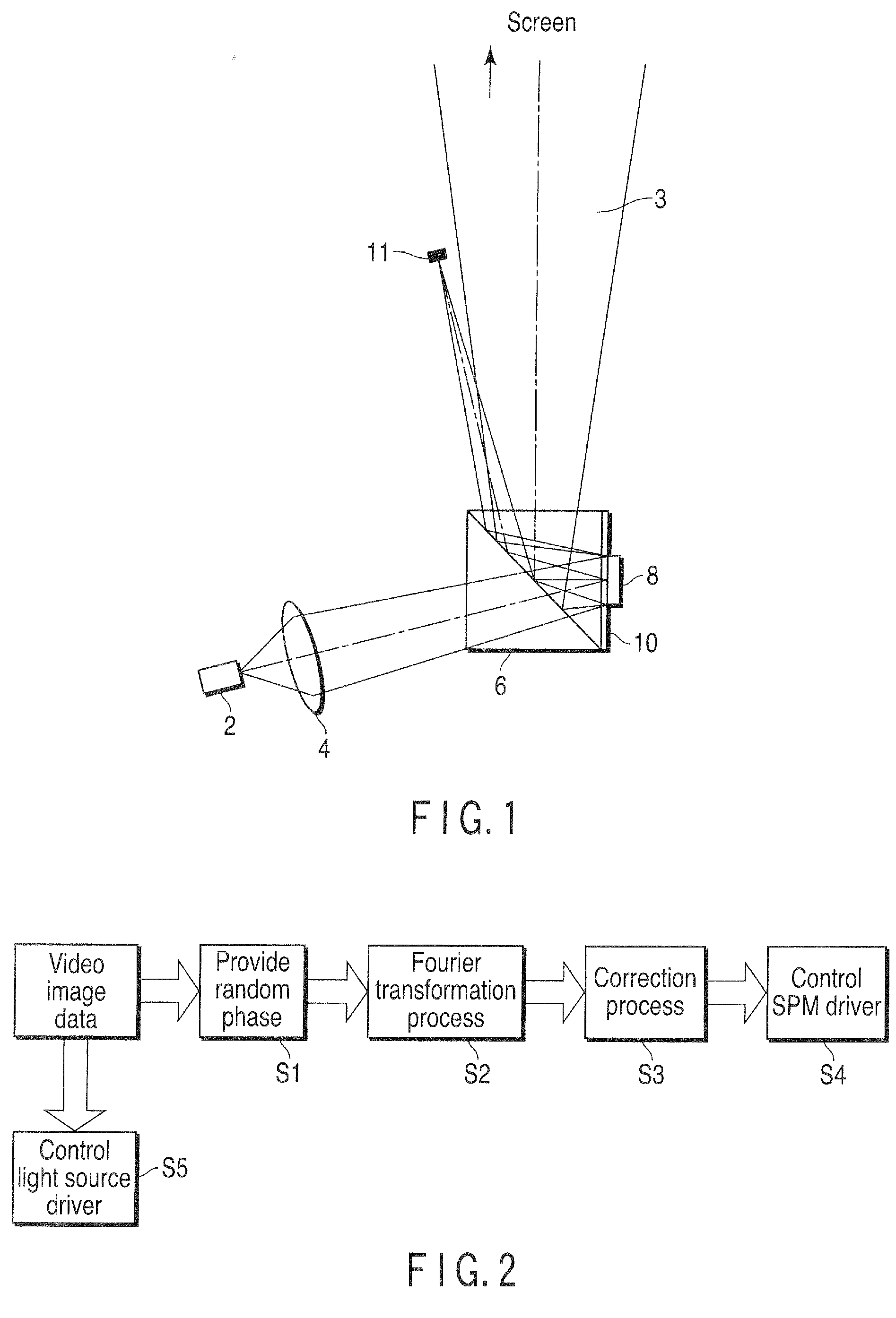
[0115]FIG. 1 is a diagram illustrating an example of the configuration of a holographic projection device according to a first embodiment of the invention. As shown in the drawing, the holographic projection device according to the first embodiment includes a light source 2, a converging lens 4, a polarized beam splitter (PBS) 6, a SPM 8, a λ / 4 plate 10, and a zero-order light trap 11.

[0116]Light that is emitted from the light source 2 is irradiated onto the SPM 8 via the PBS 6 by the converging lens 4. Diffraction light 3 that is modulated as information displayed on the SPM 8 is reflected, passes through the PBS 6 again, and is projected onto a screen (not shown). In this case, illumination light by the light source 2 is convergent light, and in a positional relationship between constituent members in the holographic projection device disposed at a normal location, the illumination light is irradiated onto the SPM 8 from an oblique upper side.

[0117]In addition, it is assumed that ...

second embodiment

[0162]Hereinafter, a holographic projection method and a holographic projection device according to a second embodiment of the present invention will be described. In this case, the description of the same contents as the contents that are described in the first embodiment will be omitted.

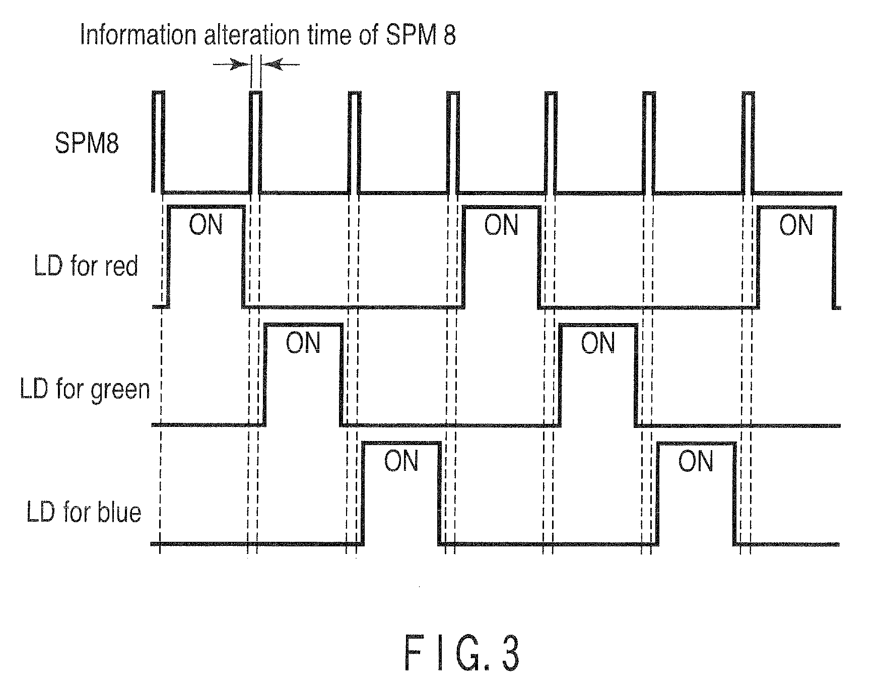
[0163]FIG. 4A is a diagram illustrating the configuration of a holographic projection device according to a second embodiment of the invention disposed at a normal location, when viewed from an upper side. FIG. 4B is a diagram illustrating the configuration of a holographic projection device according to a second embodiment of the invention disposed at a normal location, when a peripheral portion of an SPM for blue in the holographic projection device is viewed from a viewing direction E shown in FIG. 4A.

[0164]The holographic projection device according to the second embodiment includes an LD for red (not shown in FIG. 4A) that functions as a red light source, an LD for green (not shown in FIG. 4A)...

third embodiment

[0171]Hereinafter, a holographic projection method and a holographic projection device according to a third embodiment of the present invention will be described. In this case, the description of the same contents as the contents that are described in the first and second embodiments will be omitted.

[0172]FIG. 5 is a diagram illustrating the configuration of a holographic projection device according to a third embodiment of the invention. As shown in the drawing, the holographic projection device according to the third embodiment includes a light source 32a for red that functions as a red light source, a light source 32b for green that functions as a green light source, a light source 32c for blue that functions as a blue light source, and reflecting SPMs 34a, 34b, and 34c that correspond to the light sources for the individual colors, respectively.

[0173]In the second embodiment, three colors including red, green, and blue are synthesized by a color synthesis prism and color display...


PUM


Abstract

According to the present invention, video image data is converted into spatial frequency information using Fourier transformation. The spatial frequency information is provided to information display unit. The spatial frequency information as a phase distribution is displayed on the information display unit, light is irradiated onto the information display unit using a light source, the amount of light that is irradiated by the light source is adjusted based on the video image data. And diffraction light, which is irradiated by the light source and modulated as the spatial frequency information by the information display unit is projected onto projecting unit.

Description

CROSS REFERENCE TO RELATED APPLICATIONS[0001]This is a Continuation Application of PCT Application No. PCT / JP2008 / 053282, filed Feb. 26, 2008, which was published under PCT Article 21(2) in Japanese.[0002]This application is based upon and claims the benefit of priority from prior Japanese Patent Application No. 2007-053109, filed Mar. 2, 2007, the entire contents of which are incorporated herein by reference.BACKGROUND OF THE INVENTION[0003]1. Field of the Invention[0004]The present invention relates to a holographic projection method and a holographic projection device.[0005]2. Description of the Related Art[0006]In general, examples of a projection device that projects a video image onto a screen include a projection device using transmission type liquid crystal (LC), a projection device using reflecting liquid crystal (liquid crystal on silicon [LCOS]), and a projection device using a digital micromirror device (DMD).[0007]For example, in the projection device using liquid cryst...

Claims


Application Information

Patent Timeline
Patent Type & Authority Applications(United States)
IPC IPC(8): G03H1/08
CPCG02B26/0825G03H2210/441G03H1/2286G03H1/2294G03H2001/2218G03H2001/2271G03H2001/2297G03H2222/54G03H2223/18G03H2225/24G03H2225/32G03H2225/52G03H2225/61G03H2210/20G02B26/0841G03H2222/31G03H2240/51
Inventor HORIKAWA, YOSHIAKI
Owner OLYMPUS CORP
Why Eureka
Try Eureka