
Planar lighting device

a lighting device and planar technology, applied in the direction of lighting and heating apparatus, planar/plate-like light guides, instruments, etc., can solve the problems of uneven brightness on the light exit plane, lower light use efficiency of backlight units than direct illumination types, and decrease in thickness, so as to minimize uneven brightness, reduce unevenness, and reduce unevenness

Active Publication Date: 2009-04-23
FUJIFILM CORP
View PDF9 Cites 58 Cited by
  • Summary
  • Abstract
  • Description
  • Claims
  • Application Information

AI Technical Summary

Benefits of technology

[0013]Also proposed is a method whereby the light guide plate is provided with a reflection member near its light entrance plane on the opposite side from the light entrance plane to cause admitted light to undergo multiple reflection before allowing the light to exit through the light exit plane. To achieve a large light exit plane with these light guide plates by this method, however, the light guide plate needs to have an increased thickness, increasing weight and costs. Further, the light sources are projected into the light guide plate and perceived as such to cause uneven brightness and / or uneven illuminance.
[0014]On the other hand, the side light type backlight unit using a flat light guide plate contains fine scattering particles dispersed therein in order to efficiently emit admitted light through the light exit plane. Although such a flat light guide plate may be capable of securing a light use efficiency of 83% at a particle density of 0.30 wt %, its brightness dropped in an area about the center as illustrated by the illuminance distribution indicated by a solid line in FIG. 30 when it was adapted to provide a larger screen despite scattering particles evenly dispersed therein, thus allowing uneven brightness to stand out to a visible level.
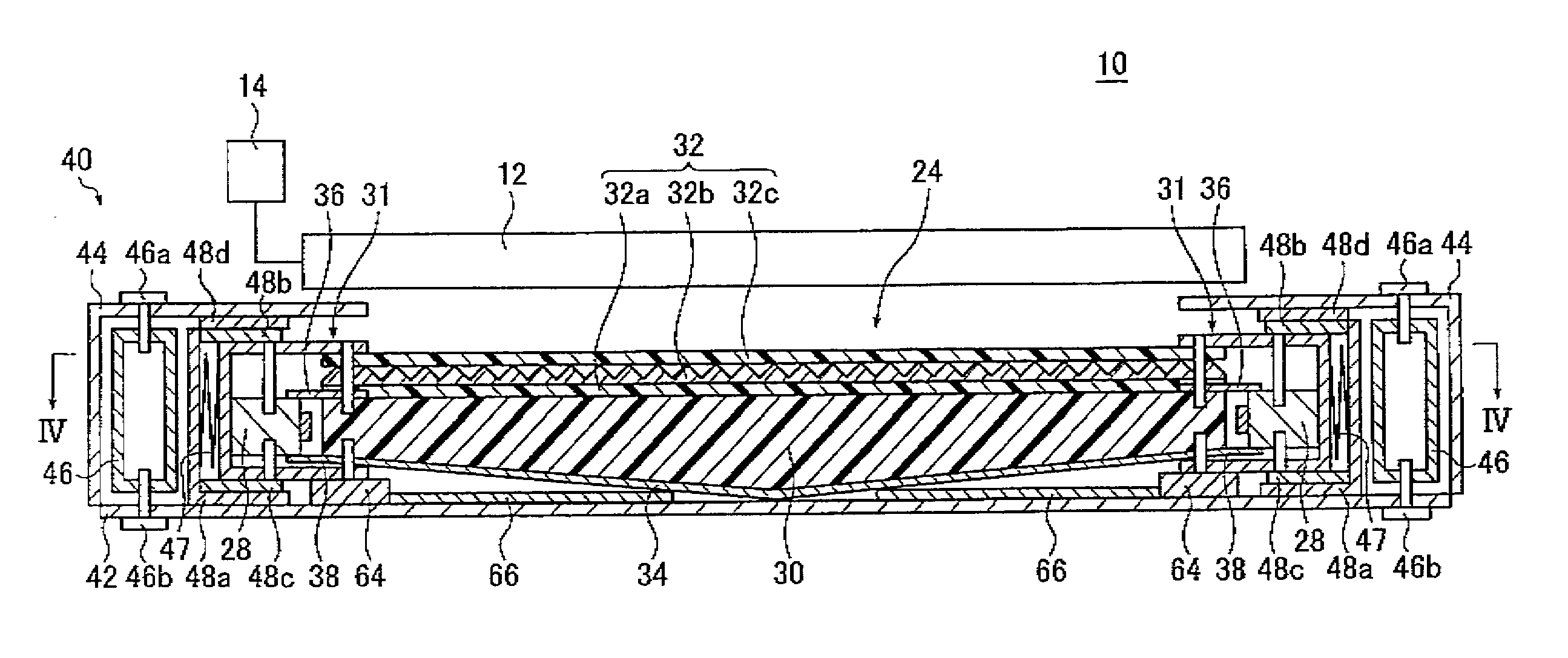
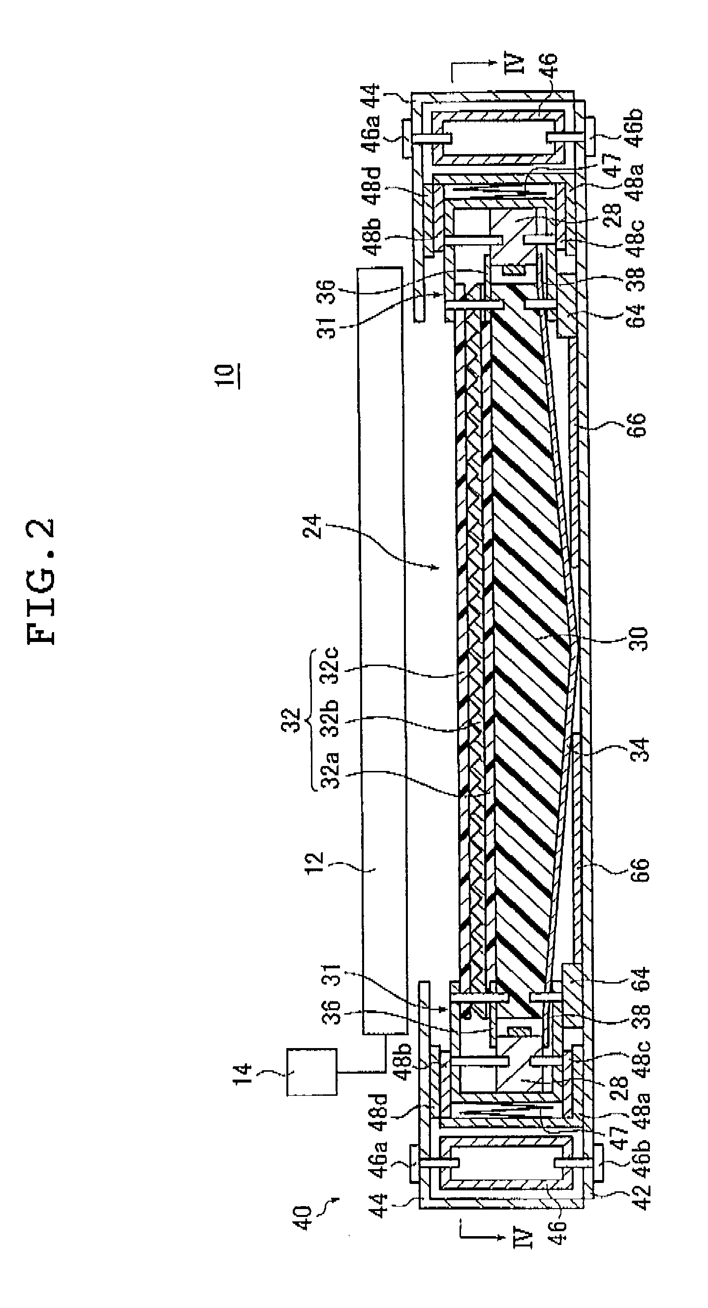
[0019]It is an object of the invention to provide a light guide plate that solves the problems associated with the prior art mentioned above and which has a large and thin configuration, yields a high light use efficiency, emits light with minimized unevenness in brightness, and achieves a brightness distribution representing a high-in-the-middle curve or a bell curve, whereby an area close to the center of the screen is brighter than the periphery thereof as required of thin, large-screen liquid crystal televisions.
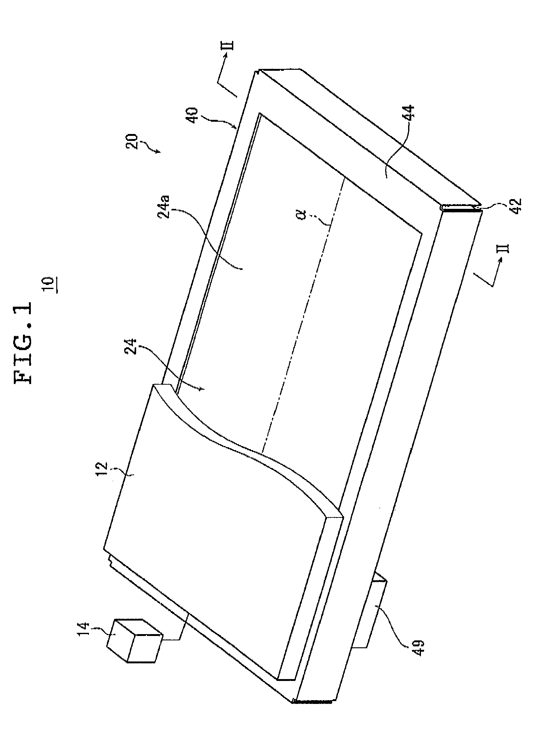
[0043]The present invention provides a planar lighting device that has a thin configuration, yields a high light use efficiency, emits light with minimized unevenness in brightness, and achieve a brightness distribution representing a high-in-the-middle curve or a bell curve, whereby an area close to the center of the screen is brighter than the periphery thereof as required of thin, large-screen liquid crystal televisions.

Problems solved by technology

While a thin design may be achieved with backlight units such as the tandem type, of which the thickness decreases with the increasing distance from the light source, those backlight units yielded lower light use efficiency than the direct illumination type because of the relative dimensions of the cold cathode tube to the reflector.
Further, where the light guide plate used is shaped to have grooves for receiving cold cathode tubes, although such a light guide plate could be shaped to have a thickness that decreases with the increasing distance from the cold cathode tube, if the light guide plate is made thinner, brightness at locations immediately above the cold cathode tube disposed in the grooves increased, thus causing uneven brightness on the light exit plane to stand out.
In addition, all these light guide plates posed further problems: complex configurations leading to increased machining costs.
Thus, a light guide plate of any of such types adapted to be used for a backlight unit for a large liquid crystal television having a screen size of say 37 inches or larger, in particular 50 inches or larger, was considerably expensive.
To achieve a large light exit plane with these light guide plates by this method, however, the light guide plate needs to have an increased thickness, increasing weight and costs.
Further, the light sources are projected into the light guide plate and perceived as such to cause uneven brightness and / or uneven illuminance.

Method used


Image

  • Planar lighting device
  • Planar lighting device
  • Planar lighting device

Examples


example 1

[0310]In Example 1, the light guide plate 30 having a light guiding length L of 480 mm for a screen size of 37 inches was used to obtain the taper, the radius of curvature R of the central portion (curved portion) [mm], the light use efficiency [%], and the middle-high ratio [%] by varying the maximum thickness [mm], the minimum thickness [mm], the particle diameter [μm], and the particle density [wt %] as shown in Tables 5 and 6. Tables 5 and 6 show the results.

[0311]Table 5 shows examples 11 to 16 according to the invention related to Example 1; Table 6 shows Comparative Examples 11 to 15 related to Example 1.

TABLE 5Example 1Examples according to the invention111213141516Screen size37″37″37″37″37″37″Light guiding480480480480480480length [mm]Maximum3.481.493.513.483.483.48thickness [mm]Minimum20.51222thickness [mm]Particle7774.5912diameter [μm]Particle0.0650.0490.0970.0470.0840.122density[wt %]Taper0.4770.3580.7160.4770.4770.477Central15000270007000150001500015000portion R [mm]Ligh...

example 2

[0317]In Example 2, light guide plates 30 having light guiding lengths L of 560 mm and 590 mm for screen sizes of 42 inches and 46 inches, respectively, were used to obtain the taper, the radius of curvature R of the central portion (curved portion), the light use efficiency [%], and the middle-high ratio [%] by varying the maximum thickness [mm], the minimum thickness [mm], the particle diameter [μm], and the particle density [wt %] as shown in Tables 7 and 8. Tables 7 and show the results.

[0318]Table 7 shows examples 21 to 24 according to the invention related to Example 2; Table 8 shows Comparative Examples 21 to 23 related to Example 2.

TABLE 7Example 2Examples accordingto the invention21222324Screen size42″46″42″46″Light guiding560590560590length [mm]Maximum thickness3.483.483.483.5[mm]Minimum thickness2221.5[mm]Particle diameter77127[μm]Particle density0.0480.0430.090.054[wt %]Taper0.4110.390.4110.486Central portion R20000220002000015000[mm]Light use61616159efficiency [%]Middle...

example 3

[0322]In Example 3, light guide plates 30 having light guiding lengths L of 660 mm and 730 mm for screen sizes of 52 inches and 57 inches, respectively, were used to obtain the taper, the radius of curvature R of the central portion (curved portion), the light use efficiency [%], and the middle-high ratio [%] by varying the maximum thickness [mm], the minimum thickness [mm], the particle diameter [μm], and the particle density [wt %] as shown in Tables 9 and 10. Tables 9 and 10 show the results.

[0323]Table 9 shows examples 31 and 32 according to the invention related to Example 3; Table 10 shows Comparative Examples 31 to 35 related to Example 3.

TABLE 9Example 3Example accordingto the invention3132Screen size52″57″Light guiding length660730[mm]Maximum thickness [mm]3.53.48Minimum thickness [mm]22Particle diameter [μm]77Particle density0.0350.028[wt %]Taper0.3510.317Central portion R [mm]2800033000Light use efficiency6061[%]Middle-high ratio [%]1414.2

TABLE 10Comparative ExampleCompar...


PUM


Abstract

The planar lighting device includes a light guide plate including two symmetrical, inclined planes increasingly distanced from the light exit plane with the increasing distance from the light entrance planes toward the center, a curved portion joining the inclined planes, and scattering particles dispersed therein; light sources; a housing; a securing unit securing the light sources and light guide plate to keep their distance constant, and a sliding mechanism allowing the securing unit to slide. Distance between the light entrance planes, thicknesses at the light entrance planes and at the central curved portion, its radius of curvature and taper of the inclined planes are all held within respective given ranges as well as scattering particle diameter and density, light use efficiency and middle-high ratio of the brightness distribution. A thin planar lighting device yielding high light use efficiency with a minimized brightness unevenness and a high-in-the-middle brightness distribution.

Description

[0001]The entire contents of literature cited in this specification are incorporated herein by reference.BACKGROUND OF THE INVENTION[0002]The present invention relates to a planar lighting device used for a liquid crystal display device and like devices.[0003]Liquid crystal display devices use a backlight unit for radiating light from behind the liquid crystal display panel to illuminate the liquid crystal display panel. A backlight unit is configured using a light guide plate for diffusing light emitted by an illuminating light source to irradiate the liquid crystal display panel and optical parts such as a prism sheet and a diffusion sheet for rendering the light emitted from the light guide plate uniform.[0004]Currently, large liquid crystal televisions predominantly use a so-called direct illumination type backlight unit comprising a light guide plate disposed immediately above the illuminating light source. This type of backlight unit comprises a plurality of cold cathode tubes...

Claims


Application Information

Patent Timeline
Patent Type & Authority Applications(United States)
IPC IPC(8): F21V8/00
CPCG02B6/0041G02B6/0046G02B6/0051G02B6/0053G02B6/0091G02B6/0065G02B6/0068G02B6/0085G02B6/0088G02B6/0055
Inventor IWASAKI, OSAMU
Owner FUJIFILM CORP
Learn More