Synchronization detecting circuit and multimode wireless communication apparatus
- Summary
- Abstract
- Description
- Claims
- Application Information
AI Technical Summary
Benefits of technology
Problems solved by technology
Method used
Image

Examples
first exemplary embodiment
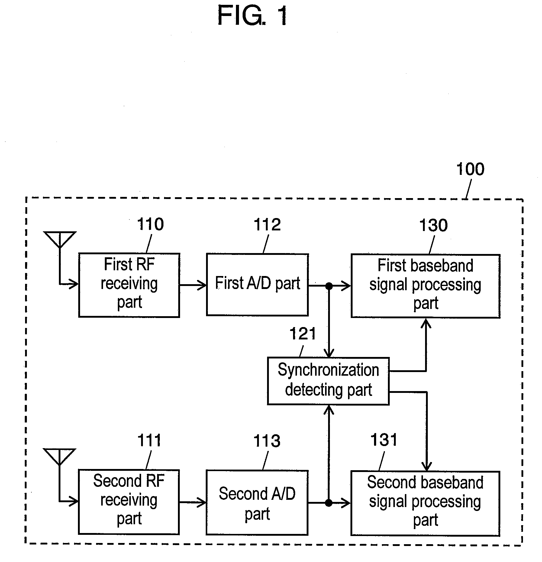
[0066]FIG. 1 is a block diagram illustrating makeup of multimode wireless communication apparatus 100 according to the first exemplary embodiment of the present invention.
[0067]In FIG. 1, multimode wireless communication apparatus 100 includes first RF receiving part 110, second RF receiving part 111, first A / D part 112, second A / D part 113, synchronization detecting part 121, first baseband signal processing part 130 as a first signal processing part, and second baseband signal processing part 131 as a second signal processing part.
[0068]First RF receiving part 110, first A / D part 112, and first baseband signal processing part 130 process a radio-frequency signal of a first wireless system in a first wireless communication method; and second RF receiving part 111, second A / D part 113, second baseband signal processing part 131 process a radio-frequency signal of a second wireless system in a second wireless communication method.
[0069]First RF receiving part 110 converts the radio-f...
second exemplary embodiment
[0101]In the first embodiment, the sampling frequency is set to the same one that is the minimum from among integral multiples of sampling rates or chip rates in different wireless communication methods. In the second embodiment, the sampling frequency is set to an integral multiple of the larger one out of sampling rates or chip rates in the first and second wireless systems. In the second embodiment, the first wireless system is assumed to use IEEE 802.11a; and the second, W-CDMA as well as in the first embodiment. For example, the sampling frequency is assumed to be 80 MHz, which is 4 times a sampling rate of 20 M samples / second in IEEE 802.11a of the first wireless system with the larger sampling rate.
[0102]FIG. 8 is a block diagram illustrating makeup of synchronization detecting part 121 of multimode wireless communication apparatus 100 according to the second embodiment of the present invention. In FIG. 8, the second embodiment is different from the first in that synchronizat...
third exemplary embodiment
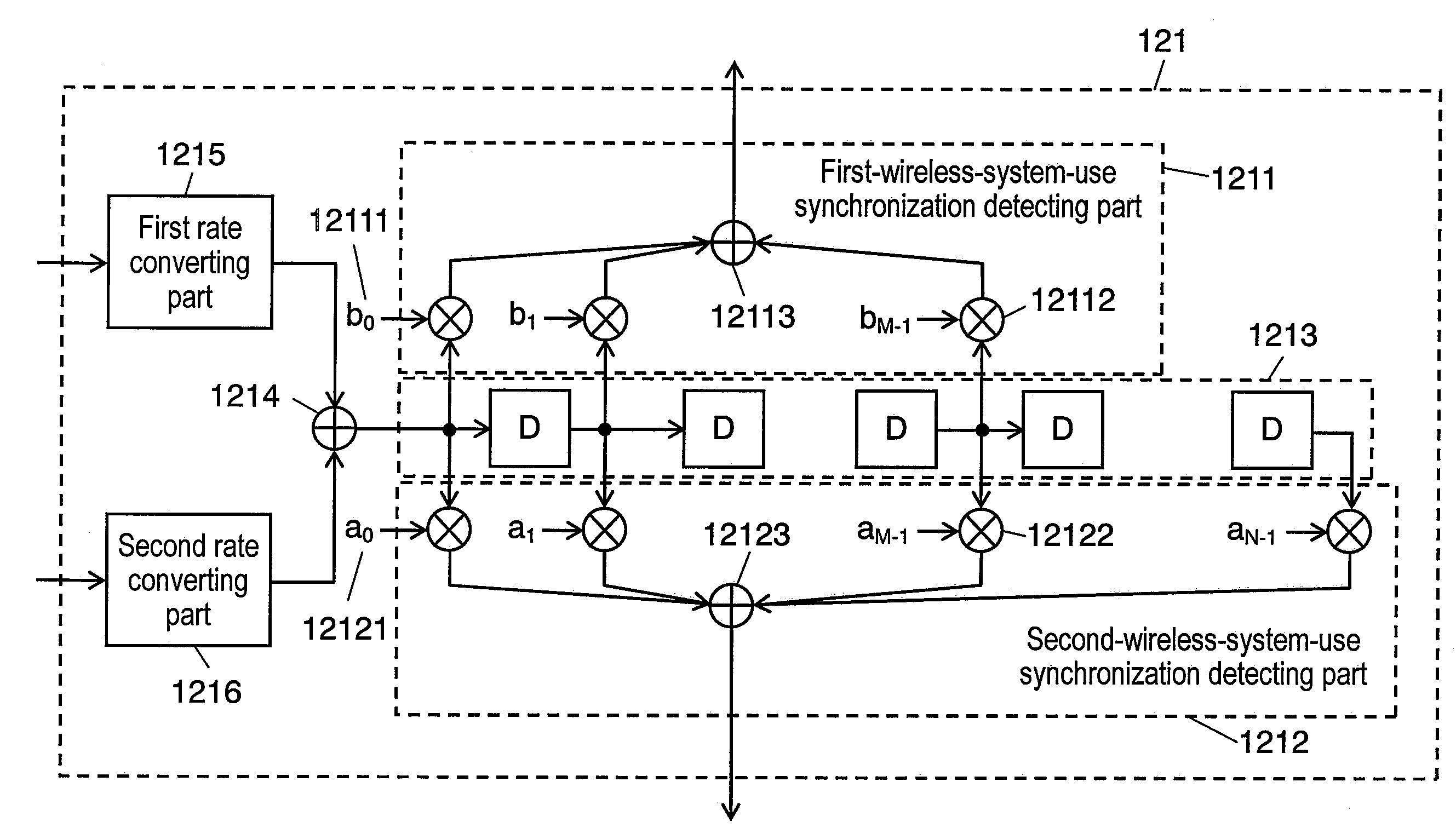
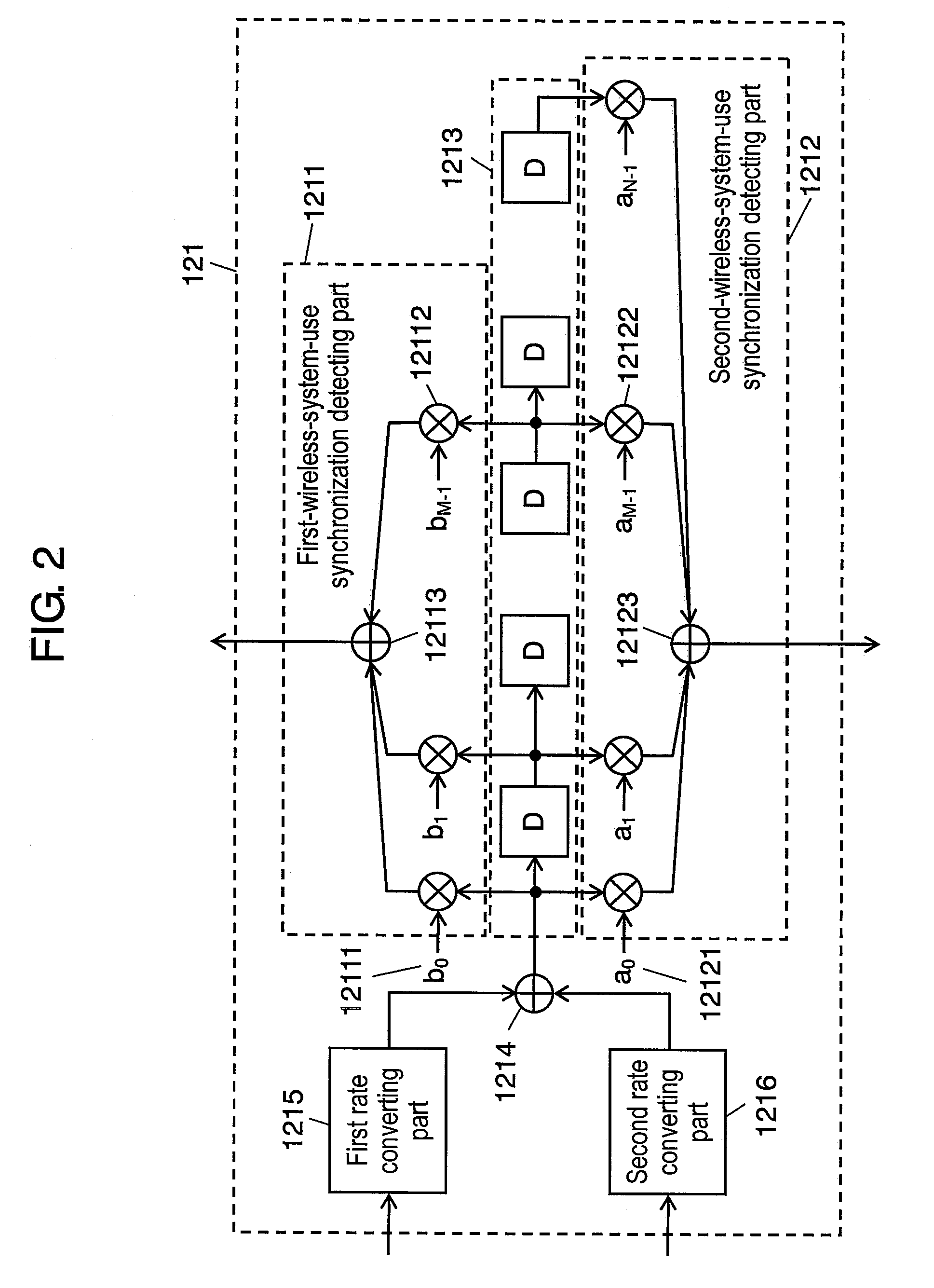
[0114]FIG. 12 is a block diagram illustrating makeup of synchronization detecting part 321 of multimode wireless communication apparatus 100 according to the third embodiment of the present invention.
[0115]Synchronization detecting part 321 in FIG. 12 is different from synchronization detecting part 121 in FIG. 2 in that part 321 has first buffer 3215 as the first converting part and second buffer 3216 as the second converting part, instead of first rate converting part 1215 as the first converting part and second rate converting part 1216 as the second converting part, in FIG. 2, and in that part 321 further has control part 320 directing output to the first and second buffers.
[0116]Control part 320 outputs a control signal to first buffer 3215 and second buffer 3216 so that digital signals stored in first buffer 3215 and second buffer 3216 will be output when detecting synchronization timing becomes necessary.
[0117]First buffer 3215 outputs the digital signals stored until detecti...
PUM
 Abstract
Description
Claims
Application Information