
Acoustic signal packet communication method, transmission method, reception method, and device and program thereof

Inactive Publication Date: 2009-04-23
NIPPON TELEGRAPH & TELEPHONE CORP
View PDF14 Cites 19 Cited by
  • Summary
  • Abstract
  • Description
  • Claims
  • Application Information

AI Technical Summary

Benefits of technology

[0012]The use of the packet-loss concealment technique described in Non-patent literature 1 in a communication environment where packet loss occurs has the effect of reducing degradation of quality of reproduced sound to some extent. However, if a packet loss occurs near the boundary between a consonant and a vowel, uncomfortable noise cannot sufficiently be eliminated. Furthermore, if the packets of consecutive multiple frames are lost, unnatural perceived reproduction sound quality will result.
[0020]According to the present invention, the delay amount control information is contained in a packet and sent and acoustic signal corresponding data of each frame is sent in another packet. That is, even if the amount of delay is changed at the sending end, the relation between the acoustic signal and the acoustic signal corresponding data can be known at the receiving end. Therefore, if the acoustic signal of a frame is lost due to a packet loss, the packet of the data corresponding to the acoustic signal can be received without a packet loss and can be readily obtained from the transmitted delay amount control information.
[0022]In this way, real-time stable acoustic communication can be performed over a packet communication network on which the frequency of packet losses is high. Packet communication networks are typically designed in such a manner that they tolerate a certain degree of packet losses to reduce cost. The present invention also has the effect of reducing network costs because the use of the present invention can eliminate the need for designing high-quality transmission circuits with low packet loss rates.

Problems solved by technology

However, if a packet loss occurs near the boundary between a consonant and a vowel, uncomfortable noise cannot sufficiently be eliminated.
Furthermore, if the packets of consecutive multiple frames are lost, unnatural perceived reproduction sound quality will result.
However, the literature does not show how many frames (the amount of delay) after the acoustic signal frame its side information should be transmitted simultaneously with an acoustic signal frame.
Communication conditions in a real communication network changes and accordingly jitter of packets and the frequency of packet losses change.
However, none of the conventional-art techniques show a method for dynamically changing the amount of delay.
Furthermore, the amount of delay must be determined beforehand between the end devices.

Method used


Image

  • Acoustic signal packet communication method, transmission method, reception method, and device and program thereof
  • Acoustic signal packet communication method, transmission method, reception method, and device and program thereof
  • Acoustic signal packet communication method, transmission method, reception method, and device and program thereof

Examples


first embodiment

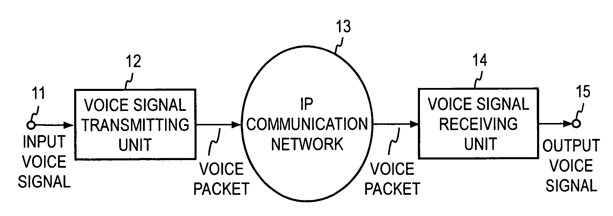
[0061]FIG. 7 shows an exemplary functional configuration of a voice signal transmitting apparatus 100 (which corresponds to the transmitting unit 12 shown in FIG. 1); FIG. 8 shows an exemplary functional configuration of a voice signal receiving apparatus 200 (which corresponds to the receiving unit 14 shown in FIG. 1); FIG. 9 shows an example of a process performed in the voice signal transmitting apparatus 100; FIG. 10 shows a process performed in the voice signal receiving apparatus 200.

Sending End

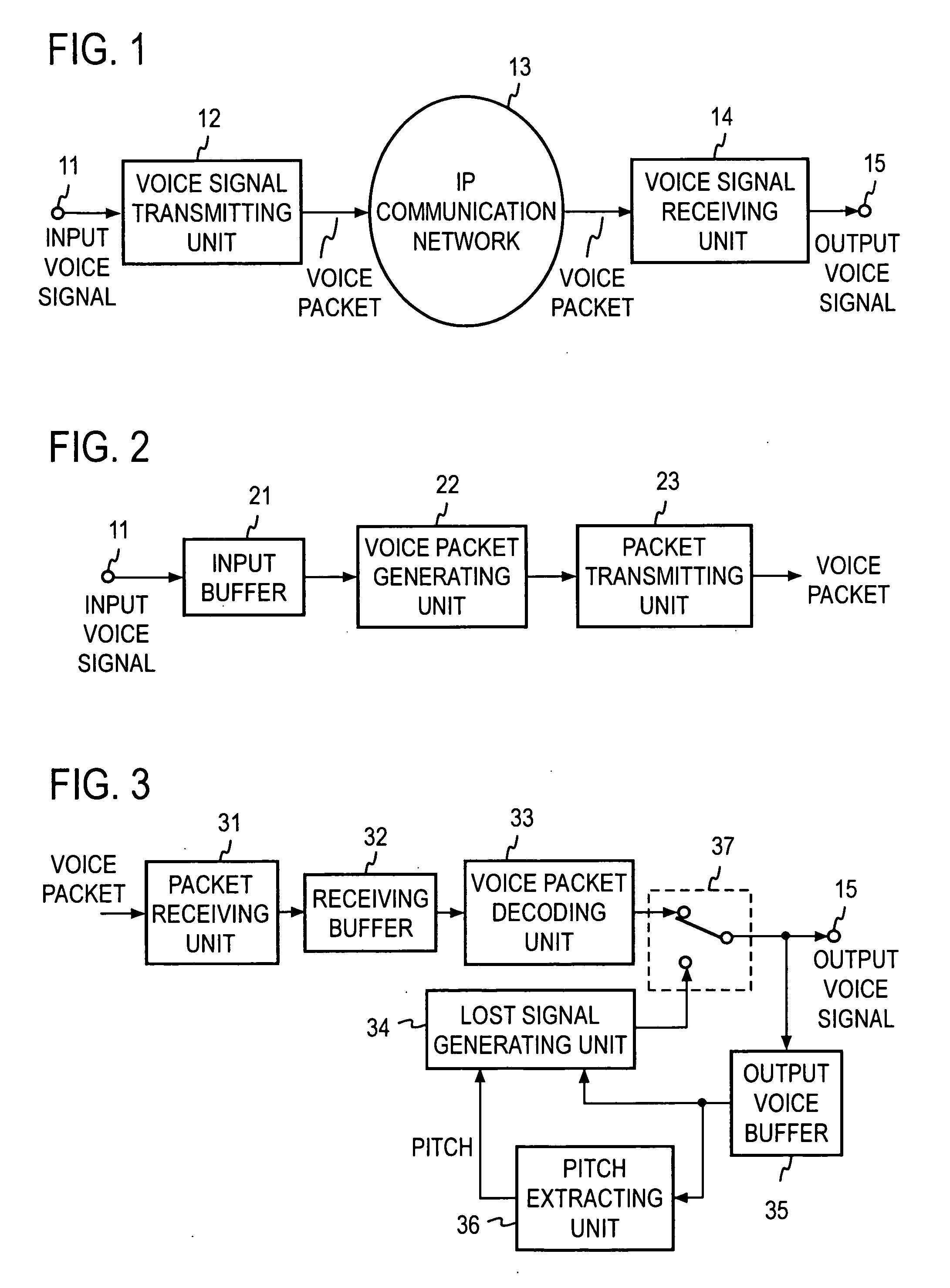
[0062]In the transmitting apparatus 100, an input voice signal is stored in an input buffer 111, divided into given time segments called frames, that is, divided into frames (step S1), and then sent to a voice waveform coding unit 112. The time length of one frame is typically 10 to 20 milliseconds or so. The voice waveform coding unit 112 uses for example G.711 (μ-law PCM or A-law PCM), which is an ITU-T standard coding algorithm, to convert the input voice signal into a voice code (st...

second embodiment

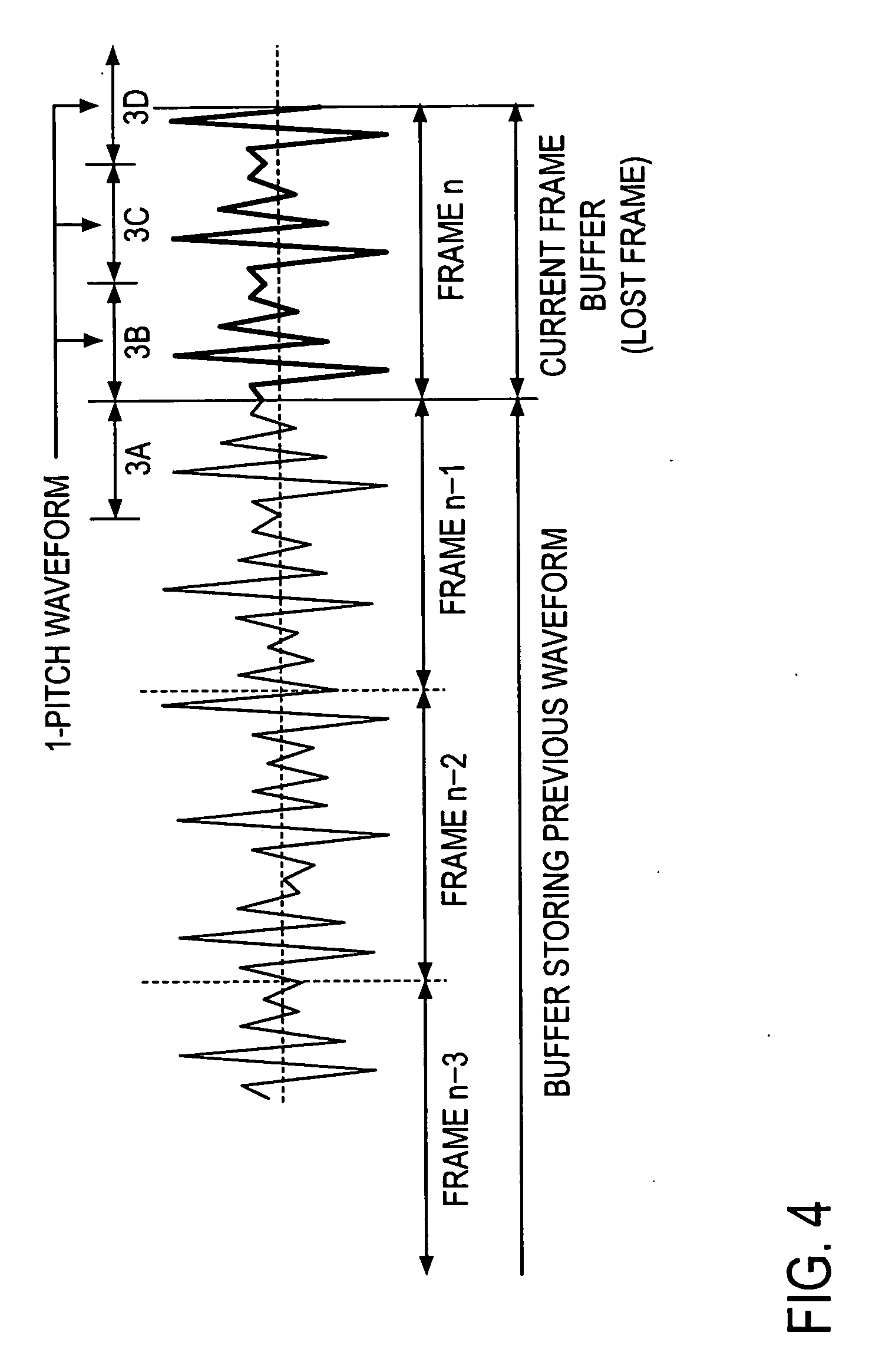
[0097]In the first embodiment, inclusion and transmission of voice features in a packet different from a voice signal frame, the use of the remaining buffer amount at the receiving end to control the amount of delay of voice features with respect to the voice signal, and a method for generating a lost frame when a packet loss occurs have been described with respect to the voice signal transmitting apparatus 100 and voice signal receiving apparatus 200. In a second embodiment, a method for controlling the amount of delay by using information other than a remaining buffer amount will be described. Furthermore, information included and transmitted in a packet different from a voice signal packet is not limited to voice features but instead they will be described as data corresponding to an acoustic signal (hereinafter referred to as “acoustic signal corresponding data”). This is because when a packet is lost, the lost frame may be generated in a method other than generating from acoust...


PUM


Abstract

When acoustic signal packets are communicated over an IP communication network, data corresponding to an acoustic signal (acoustic signal corresponding data) has been included and transmitted in a packet different from a packet containing the acoustic signal. However, conventionally, a packet in which the acoustic signal corresponding data is to be included must be determined beforehand and cannot dynamically be changed.According to the present invention, the amount of delay of acoustic signal corresponding data with respect to an acoustic signal is contained in an acoustic signal packet as delay amount control information. Furthermore, the conditions of a communication network are detected from the number of packets lost in a burst loss or jitters and the number of the packets to be stored and the amount of delay at the receiving end are thereby determined.

Description

TECHNICAL FIELD[0001]The present invention relates to a communicating method, transmitting method, and receiving method that provide measures against packet loss during transmission of acoustic signals such as digitized voice and music over a packet communication network such as the Internet, and to an apparatus and program therefor.BACKGROUND ART[0002]Services using Voice over IP (Internet Protocol) technology to transmit voice signals is becoming widespread. As shown in FIG. 1, a voice signal from an input terminal 11 is converted in a voice signal transmitting unit 12 into voice packets, transmitted over a packet communication network 13 such as an IP network to a voice signal receiving unit 14, where the voice signal is reproduced and outputted to an output terminal 15. There exists a problem that when packets are communicated in real time, packet losses can occur on the packet communication network 13 depending on the conditions of the network, causing quality degradation such ...

Claims


Application Information

Patent Timeline
IPC IPC(8): H04L12/66G10L19/00G10L19/005
CPCG10L19/005G10L19/167H04L65/80H04L65/607H04L65/602H04L65/762H04L65/70
Inventor OHMURO, HITOSHIMORI, TAKESHIHIWASAKI, YUSUKEKATAOKA, AKITOSHI
Owner NIPPON TELEGRAPH & TELEPHONE CORP
Features
  • Generate Ideas
  • Intellectual Property
  • Life Sciences
  • Materials
  • Tech Scout
  • Unparalleled Data Quality
  • Higher Quality Content
  • 60% Fewer Hallucinations
Learn More