Rolling bearing unit for supporting a wheel and the manufacturing method thereof

a technology of rolling bearings and manufacturing methods, which is applied in the direction of manufacturing tools, transportation and packaging, portable lathes, etc., can solve the problems of easy vibration and noise, and achieve the effects of improving the positional relationship, and improving the parallelism of on

Inactive Publication Date: 2009-04-23
NSK LTD
View PDF3 Cites 2 Cited by
  • Summary
  • Abstract
  • Description
  • Claims
  • Application Information

AI Technical Summary

Benefits of technology

[0022]As described above, with the wheel-supporting rolling bearing unit and manufacturing method thereof of the present invention, it is possible to sufficiently maintain the parallelism between the stationary side installation on which the support or caliper is installed, and the rotating side installation surface on which the disk is installed or the pair of braking friction surfaces formed on the disk. More specifically, when the rotating section is the rotating side installation surface on which the disk is installed, it is possible to improve the parallelism of one of the installation surfaces, either the rotating side installation surface or stationary side installation surface, with respect to the other installation surface. Therefore, it is possible to improve the positional relationship between the disk that is installed on the rotating side installation surface and the support or caliper that is installed on the stationary side installation surface. Also, when the rotating section is a pair of braking friction surfaces that are formed on the disk, it is possible to improve the positional relationship between the braking friction surfaces and the support or caliper that is installed on the stationary side installation surface. Therefore, when manufactured using either manufacturing method, it is possible to improve the state of contact between the both braking friction surfaces that are formed on the disk and the pair of pads that are attached to the support or caliper when braking. As a result, judder that occurs during braking can be suppressed.
[0023]Also, in the case of the present invention, a flat surface proc...

Problems solved by technology

Also, as this nonuniform level becomes large, it becomes easy for ...

Method used


Image

  • Rolling bearing unit for supporting a wheel and the manufacturing method thereof
  • Rolling bearing unit for supporting a wheel and the manufacturing method thereof
  • Rolling bearing unit for supporting a wheel and the manufacturing method thereof

Examples


second embodiment

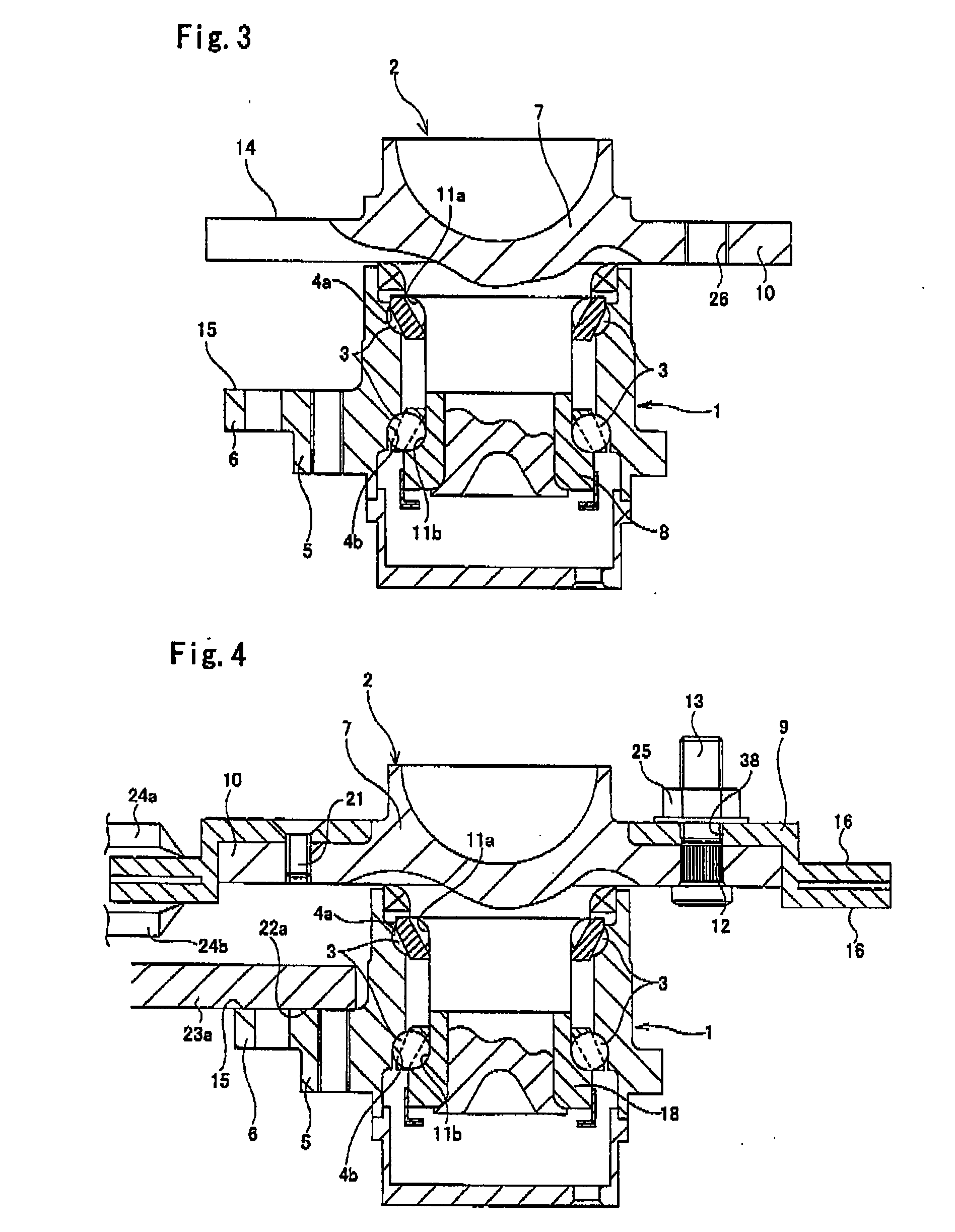
[0051]FIG. 4 and FIG. 5 show a second embodiment of the invention. The feature of this embodiment is a method of performing a turning process as the finishing process for the pair of braking friction surfaces 16 that are both side surfaces on the outer end section in the radial direction of the disk 9, and for the stationary side installation surface 15 that is the outside surface of the stationary side support flange 6. The basic construction of the wheel-supporting rolling bearing unit with the disk of this embodiment and the construction and function of other parts are the same as in the case of the wheel-supporting rolling bearing unit with a disk shown in FIG. 18 and described above. Therefore, the same reference numbers are given to identical parts, and any redundant explanation is omitted or simplified, so that the explanation here centers on the features of this embodiment.

[0052]As shown in FIG. 4, in this embodiment, for the wheel-supporting rolling bearing unit with disk i...

third embodiment

[0060]FIG. 7 and FIG. 8 show a third embodiment of the present invention. In this embodiment, even when the space between the outside surface in the axial direction of the stationary side support flange 6 and the inside surface in the axial direction of the rotating side support flange 10 is narrow, it is the intention of this embodiment to improve the parallelism between the outside surface in the axial direction of the stationary side support flange 6 (stationary side installation surface 15) and the inside surface in the axial direction of the rotating side support flange 10. In other words, in the case of a compact wheel-supporting rolling bearing unit, the space between the outside surface in the axial direction of the stationary side support flange 6 and the inside surface in the axial direction of the rotating side support flange 10 is narrow, and when left as is, there is a possibility that the outside surface in the axial direction of the stationary side support flange 6 ca...

fourth embodiment

[0064]FIG. 9 shows a fourth embodiment of the present invention. In this embodiment, the outside surface in the axial direction of the stationary side support flange 6 that is formed on the outer peripheral surface of the outer race 1 (stationary side installation surface 15) is used as a reference, and in order to finish the outside surface in the axial direction of the rotating side support flange 10 that is formed around the outer peripheral surface of the hub 2 (rotating side installation surface 14), in the state that the hub 2 is still held (by one-chuck), the outer peripheral surface of a positioning cylindrical section 27 that is formed around the section situated nearer the inner radial side of the outside surface in the axial direction of the rotating side support flange 10 (section indicated by the dotted line in FIG. 9) is also finished. This positioning cylindrical section 27 makes it possible to perform positioning in the radial direction of the disk 9 (for example, re...


PUM

PropertyMeasurementUnit
Weightaaaaaaaaaa
Forceaaaaaaaaaa

Abstract

To realize a manufacturing method for a wheel-supporting rolling bearing unit that can establish sufficient parallelism between a rotating side installation surface 14 for fastening to and supporting a disk of a disk brake and a stationary side installation surface 15 for fastening a caliper or support, in the present invention, while rotating a hub 2 comprising the rotating side installation surface 14 with respect to an outer race comprising the stationary side installation surface, a finishing process such as turning is performed on the rotating side installation surface 14 or both side surfaces in the axial direction of the disk which is fastened and supported to and by the rotating side installation surface 14, with the stationary side installation surface 15 as a reference surface.

Description

BACKGROUND OF THE INVENTION[0001]This invention relates to a rolling bearing unit that supports an automobile wheel and a disk of a disk brake so that they rotate freely with respect to the suspension, as well as supports a caliper or support of the disk brake, and relates to the manufacturing method thereof.[0002]The wheel of an automobile, and the disk of a disk brake are supported by a rolling bearing unit for wheel support on the knuckle of a suspension so that they can rotate freely. On the other hand, the caliper or support of the disk brake is generally fastened to and supported by the knuckle. However, from the aspect of improving assemblibility of the caliper or support in an automobile or improving the handleability of the caliper or support, in recent years, fastening and supporting the caliper or support to a member on the stationary side of the wheel-supporting rolling bearing unit has been considered. For example, construction in which a flange for fastening to and sup...

Claims


Application Information

Patent Timeline
IPC IPC(8): F16C19/50B21D53/10
CPCB23B5/02B60B27/00F16C19/186Y10T29/49492Y10T82/10Y10T29/497Y10T29/49684Y10T29/49995Y10T29/49536Y10T82/21Y10T29/49861Y10T29/49689F16C33/64F16C2326/02
Inventor ISHIKAWA, HIROAKISUZUKI, YASUNORIOTAKE, NARIHITOTAKEHARA, TETSUHIRATA, KIYOTAKAHORIKE, SHOUJIWAKABAYASHI, TETSUO
Owner NSK LTD
Why Eureka
Try Eureka