Secondary battery and manufacturing method thereof

a second battery and manufacturing method technology, applied in the field of second batteries, can solve the problems of difficult to provide the welded area of an appropriate size, the connection resistance occurring in the connected portion of the lead parts and the electrode lead parts cannot be reduced sufficiently, and the electric beam is difficult to reach deeper than the end face of the lead parts, etc., to achieve the effect of convenient handling and easy manufacturing of second batteries

Inactive Publication Date: 2009-04-23
PANASONIC EV ENERGY CO LTD
View PDF2 Cites 46 Cited by
  • Summary
  • Abstract
  • Description
  • Claims
  • Application Information

AI Technical Summary

Benefits of technology

[0060]In the manufacturing method of the secondary battery of the invention, the collector terminal member having the first and second contact portions is used. With use of this collector terminal member, the foil laminated portion is sandwiched between and in contact with the first and second contact portions of a single component placed on both sides of in the lamination direction. This enables a configuration that the foil laminated portion is tightly held between two contact portions and hence the secondary battery can be manufactured more easily.
[0061]It is preferable to deform the collector terminal member itself by crimping or the like to thereby tightly hold the foil laminated portion in close contact with and between the first and second contact portions of the collector terminal member.
[0062]Accordingly, the foil laminated portion can be kept in close contact relation to the first and second contact portions without a special member or tool after the crimping or the like, thereby allowing them to be easily handled in subsequent steps such as the welding step.

Problems solved by technology

However, the electron beam is hard to reach deeper than the end faces of the lead parts.
In such secondary battery, consequently, the connection resistance occurring in the connected portion of the lead parts and the electrode lead parts could not be reduced sufficiently.
As mentioned above, it has been difficult to provide the welded area of an appropriate size.

Method used


Image

  • Secondary battery and manufacturing method thereof
  • Secondary battery and manufacturing method thereof
  • Secondary battery and manufacturing method thereof

Examples


first embodiment

[0081]A detailed description of a first preferred embodiment of the present invention will now be given referring to the accompanying drawings.

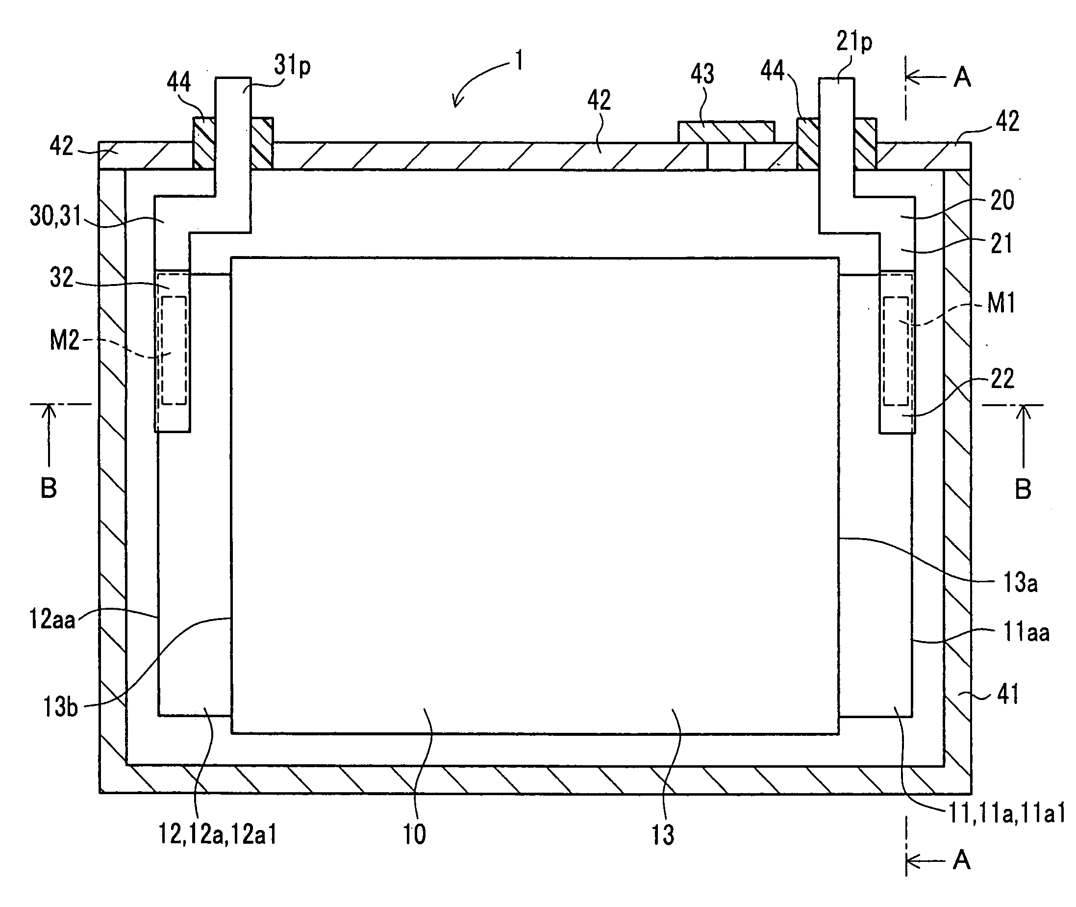
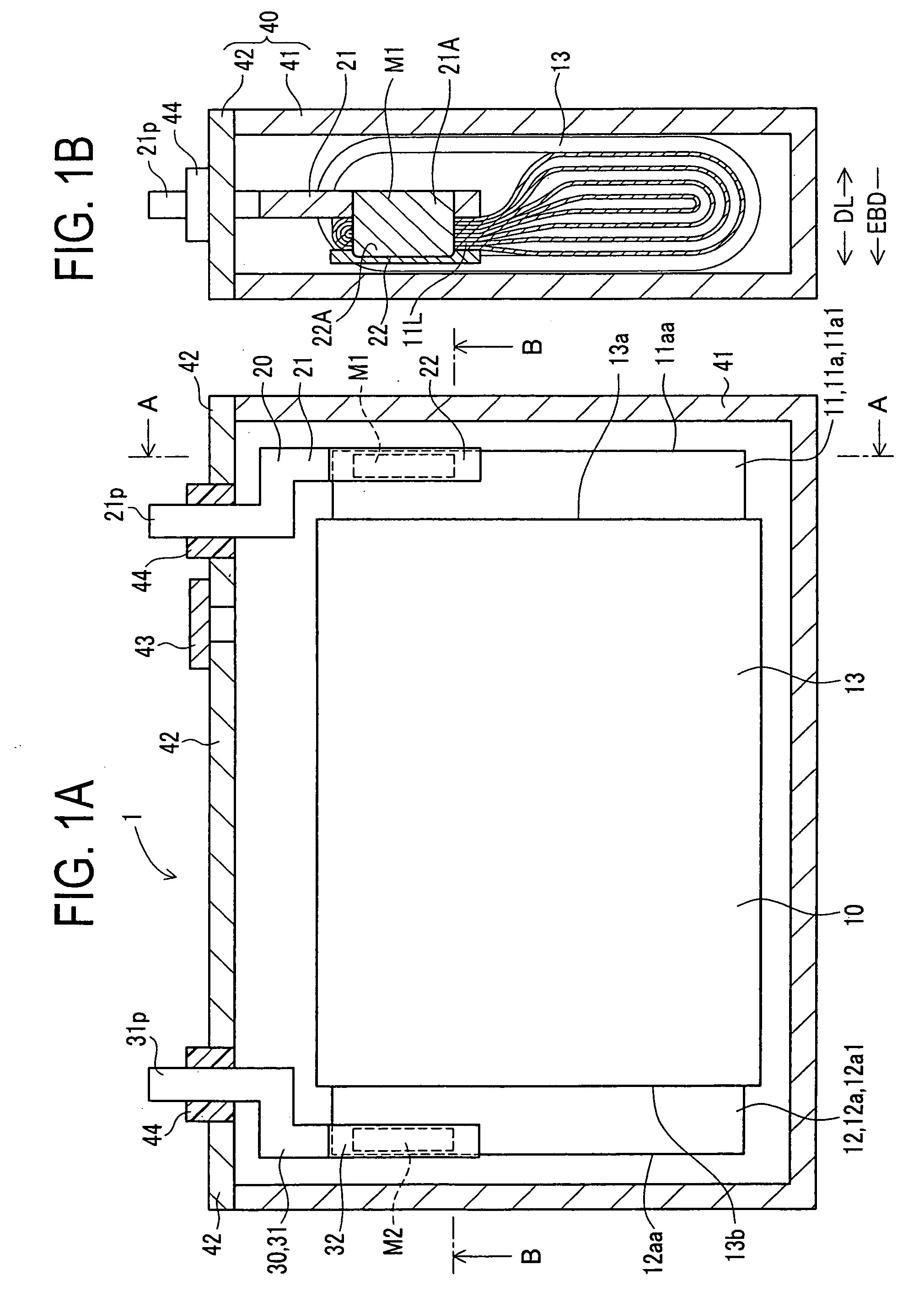
[0082]A secondary battery 1 in the first embodiment is a lithium ion secondary battery including a power generation element 10, a positive electrode collector terminal member (hereinafter, a “positive collector member”) 20, a negative electrode collector terminal member (hereinafter, a “negative collector member”) 30, and a battery case 40 as shown in FIG. 1A.

[0083]The battery case 40 includes a case body 41, a cover 42, a safety valve 43, and insulating parts 44.

[0084]The case body 41 is a metal, bottom-closed rectangular container having an upper opening. The cover 42 on which the safety valve 43 is provided is placed to close the upper opening of the case body 41. The case body 41 and the cover 42 liquid-tightly enclose the power generating element 10, the positive collector member 20, the negative collector member 30, and electrolyte not ...

modified example

[0127]A modified example of the manufacturing method of the secondary battery 1 is explained below referring to FIGS. 5A to 5C.

[0128]This example is basically the same as the first embodiment excepting the addition of a foil contacting step prior to the contacting step.

[0129]The following explanation is therefore made with a focus on the differences from the first embodiment by assigning the same reference signs to similar or identical parts or components without repeating their details. Those similar or identical parts or components provide the same operations and advantages.

[0130]The manufacturing method of the secondary battery 1 in this modified example is explained referring to FIGS. 5A to 5C.

[0131]Firstly, the flat-shaped power generating element 10 is produced in the same way as in the first embodiment (see FIG. 5A). In this state, one part and another part of the long side portion 11a1 of the positive metal foil 11a are arranged in layers but spaced with clearances to be in ...

second embodiment

[0137]A secondary battery 101 in a second embodiment will be described below referring to FIGS. 6A to 9B.

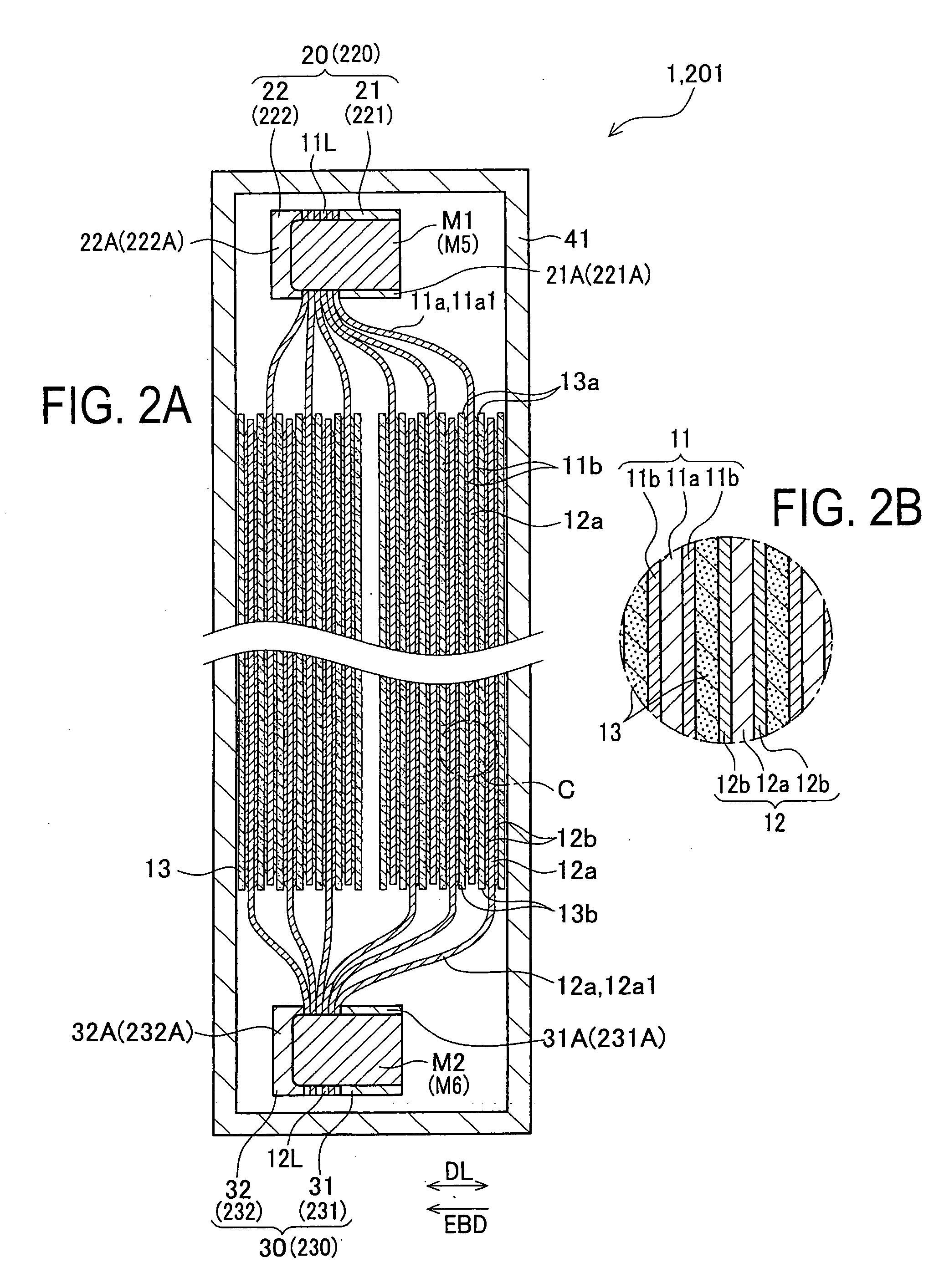
[0138]The secondary battery 1 in the first embodiment was exemplified as a configuration that, in the collector members 20 and 30, the main parts 21 and 31 and the auxiliary parts 22 and 32 are arranged so that the respective contact portions 21A, 31A, 22A, and 32A are placed in close contact with both sides of either the foil laminated portion 11L or the foil laminated portion 12L in the lamination direction DL. The secondary battery 101 in the second embodiment is similar to the secondary battery 1 in the first embodiment except that each collector terminal member includes two contact portions which are placed in close contact with both sides of each foil laminated portion.

[0139]Accordingly, the following explanation is given with a focus on the differences from the first embodiment by assigning the same reference signs to similar or identical parts or components to those in th...


PUM

PropertyMeasurementUnit
connection resistanceaaaaaaaaaa
internal resistanceaaaaaaaaaa
heataaaaaaaaaa

Abstract

In a secondary battery, a positive metal foil having a laminated portion in which parts of the metal foil are laminated in close contact with each other, and a positive electrode current collector terminal member has a contact portion placed in close contact with at least one side of the positive foil laminated portion in a lamination direction thereof The secondary battery is manufactured by welding the parts of the positive metal foil to each other and the positive foil laminated portion and the contact portion to each other by irradiation of an energy beam emitted to travel in the lamination direction while an irradiation site is moved.

Description

CROSS-REFERENCE TO RELATED APPLICATIONS[0001]This application is based upon and claims the benefit of priority from each of the prior Japanese Patent Application No. 2007-272188 on Oct. 19, 2007, the entire contents of which are incorporated herein by reference.BACKGROUND OF THE INVENTION[0002]1. Field of the Invention[0003]The present invention relates to a secondary battery in which a current collector and an electrode foil are connected by an energy beam and a manufacturing method of the secondary battery.[0004]2. Description of Related Art[0005]Regarding secondary batteries, heretofore, a connection technique by welding such as resistance welding has been employed to connect metal foils forming a positive electrode plate and a negative electrode plate to current collectors for taking out electric charges. However, a large battery to be mounted in a hybrid electric vehicle or the like needs large metal foils and large current collectors. The conventional connection technique by r...

Claims


Application Information

Patent Timeline
Patent Type & Authority Applications(United States)
IPC IPC(8): H01M6/00H01M4/00B23K15/00H01M50/538
CPCH01M2/263H01M4/661H01M10/0413Y10T29/49108H01M10/30H01M10/345H01M10/0585Y02E60/10H01M50/538
Inventor NAKAGAWA, YUGOSUZUKI, KENICHI
Owner PANASONIC EV ENERGY CO LTD
Why Eureka
Try Eureka