
Bioluminescence-based sensor with centrifugal separation and enhanced light collection

a luminescent sensor and centrifugal separation technology, applied in the field of point of care (poc) luminescent sensors, can solve the problems of not finding great commercial applicability of luminescence detectors and/or sensors in the poc, still requiring milliliter sample volumes, and requiring patients' health car

Inactive Publication Date: 2009-04-23
UNIV OF UTAH RES FOUND
View PDF15 Cites 8 Cited by
  • Summary
  • Abstract
  • Description
  • Claims
  • Application Information

AI Technical Summary

Benefits of technology

The present invention is related to a system and method for measuring multiple analytes in a sample using luminescence-based assays. The system includes a platform with a channel where the sample is introduced and contains reagents that dissolve the sample and initiate a luminescent reaction. The luminescence is then detected by a photo detector. The invention allows for series and / or parallel processing of samples and includes an on-board calibration function. The technical effects of the invention are improved accuracy and efficiency in measuring multiple analytes in a sample.

Problems solved by technology

Despite this possibility, many clinical assays still require milliliter sample volumes because their sensors are not used at the point-of-care and extra sample volume is used for transporting to the lab.
Unfortunately, such actions come at the expense of patients' health.
Luminescence detectors and / or sensors have not yet found great commercial applicability in the POC market.
A factor influencing why bioluminescence has not been readily applied to POC applications is a perception that luciferases and other reagents involved are somewhat labile, unstable, and difficult to utilize, with precise and somewhat sophisticated protocols.
{7;8;9} Although, despite the advances, there is limited work in packaging bioluminescent assays in microfluidic devices.
Most luminometers use photo-multiplier tubes (PMT) due to their high sensitivity, however, due to their large size they have not been extensively used in microfluidic multi-analytes devices.
Comparably sensitive CCDs can be used for measuring multiple luminescent reactions in parallel, but are too expensive for POC applications.
This relationship, however, does not show how the scaling effects of miniaturization can actually improve the detection limit.
Although bioluminescence-based analysis is well known and has been used regularly in research, it has not been widely applied to POC or routine clinical analysis.
Specifically, a luminescence-based device has not been created for measuring multiple analytes at the point-of-care.
Also, such a device has not been created with sample preparation functionality (blood and plasma separation).
Also, the ability to aliquot small sample volumes (less that 1 μL) to multiple reaction wells for measuring different analytes has not been implemented in a POC device.
{16} However, bioluminescence-based analysis has not been implemented on a centrifugal-based sample delivery system for POC applications.
However, aliquoting plasma to multiple sections has not been developed on a CD type device due to the low surface tension of plasma, which tends to burst past the passive valves of current art, at low spinning speeds.
Because of the problems with metering plasma by prior art passive valve, plasma separation and sample metering have not been combined on the same device.
However, the art field has not incorporated a photodetector and microfabricated centrifugal device.

Method used


Image

  • Bioluminescence-based sensor with centrifugal separation and enhanced light collection
  • Bioluminescence-based sensor with centrifugal separation and enhanced light collection
  • Bioluminescence-based sensor with centrifugal separation and enhanced light collection

Examples


examples

Fabrication of Embodiment of the Present Invention

[0091]An embodiment of a μTAS device of the present invention was microfabricated in an elastomer using “soft-lithography.” In an exemplary, non-limiting embodiment, bioluminescent detection assays for two model analyte solutions (galactose and lactate) will be stabilized in individual detection wells. An array of photo detectors was used to measure the luminescent signal from each analytical well. Sample delivery, rehydration and mixing where studied. Onboard calibration channels where cut into the platform. Blood and urine samples where tested.

[0092]The bioluminescent reagents were packaged in a stable form within the reaction wells without exposure to heat. Various microfabrication methods were tested for creating microfluidic and encapsulating them without the standard approached which involve heat and / or oxidation. The prototyping method also had to be convenient and rapid enough to be able to test a variety of sample delivery a...


PUM

PropertyMeasurementUnit
quantum efficiencyaaaaaaaaaa
volumesaaaaaaaaaa
volumesaaaaaaaaaa

Abstract

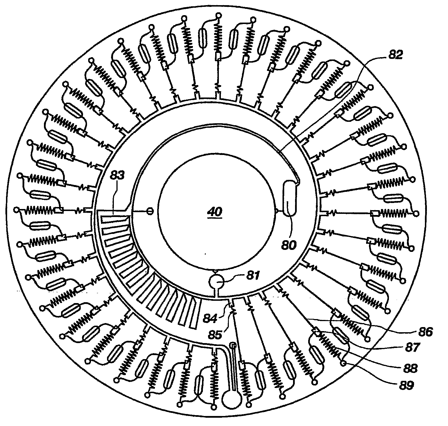
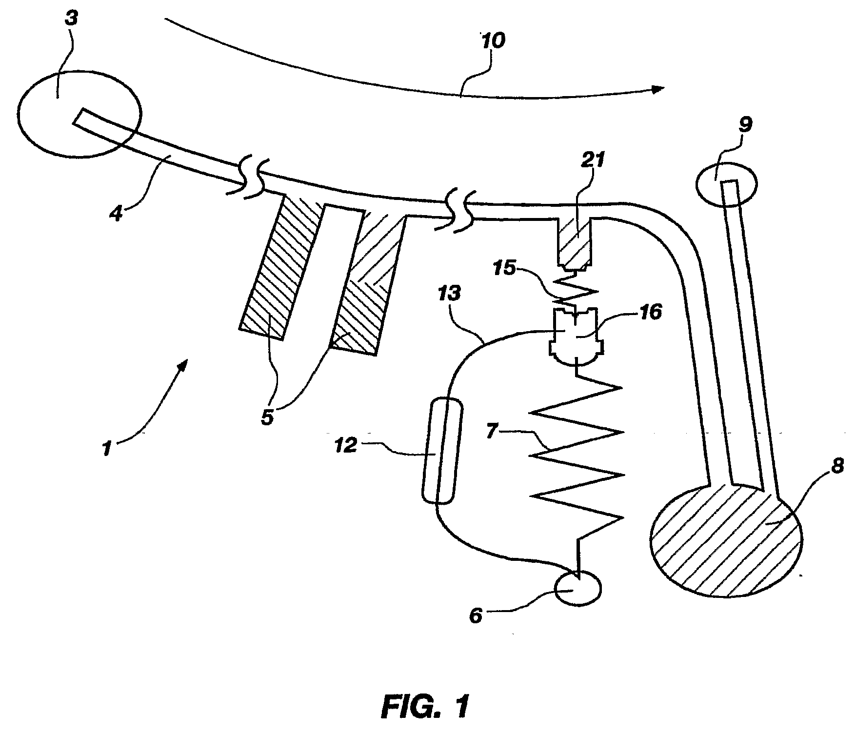
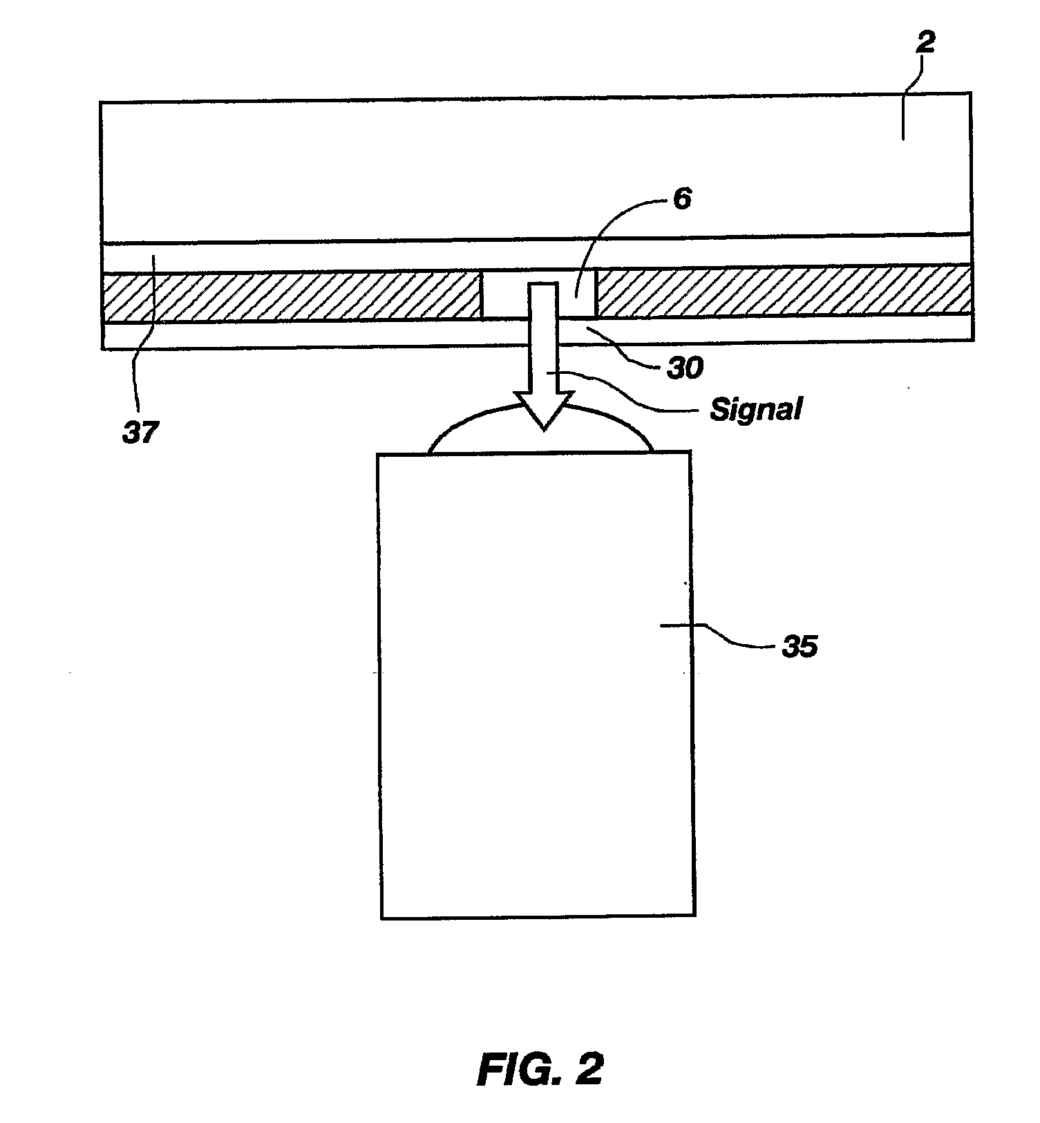
In general, embodiments of the present invention relate to a bioluminescence-based point of care device that is made up of at least one reaction well (89) that contains a bioluminescent reagent for a luminescent reaction, sample well (80), sample collection well (84), and reagent well (87). A sample is introduced into the reaction wells (89), where it dissolves the reagents and initiates the luminescent reaction, where a luminescence signal is then transmitted through a window to a photo detector.

Description

PRIORITY CLAIM[0001]This application claims the benefit, under 35 U.S.C. § 119(e), of the filing date of U.S. Provisional Patent Application Ser. No. 60 / 717,795, filed Sep. 15, 2005, for “BIOLUMINESCENCE-BASED BLOOD SENSOR WITH CENTRIFUGAL PLASMA SEPARATION, LOW TEMPERATURE ENZYME PACKAGING, AND ENHANCED LIGHT COLLECTION”, the contents of which are incorporated by this reference.GOVERNMENT LICENSE RIGHTS[0002]The work underlying this sensor was paid for, in part, by NIH RFP#PAR01-057, Project#1R21RR17329 awarded by the National Institute for Health, Technology Development for Biomedical Applications Grant. The U.S. government may have certain rights to this invention.TECHNICAL FIELD[0003]Embodiments of the present invention generally relate to point-of-care (POC) luminescent sensors, such as for use with diagnostics.BACKGROUND[0004]Point-of-Care biosensors are generally clinical quality, analytical devices used for in vitro diagnostics (“IVD”). Various of these devices have been rec...

Claims


Application Information

Patent Timeline
Patent Type & Authority Applications(United States)
IPC IPC(8): C12Q1/02C12M1/00
CPCG01N21/763G01N21/07
Inventor BARTHOLOMEUSZ, DANIEL A.
Owner UNIV OF UTAH RES FOUND
Learn More