Handle assembly for a power tool

a technology of power tools and handle assemblies, which is applied in the direction of mechanical control devices, controlling members, limiting/preventing/returning movement of parts, etc., can solve the problems of triggers, safety equipment worn, and damage to triggers, which generally protrude from the grinder housing, so as to prevent the trigger from suffering, less discomfort, and more control

Inactive Publication Date: 2009-04-23
DEMAIN TECH
View PDF15 Cites 30 Cited by
  • Summary
  • Abstract
  • Description
  • Claims
  • Application Information

AI Technical Summary

Benefits of technology

[0014]An advantage of the invention over existing gripping means and switch assemblies for holding and operating hand held power tools is that a user can grip and operate a device incorporating the invention more easily, more securely, with more control and with less discomfort. Another advantage is that a user need not grip the housing of such a device in order to operate a switch for turning the device on and off. Yet another advantage of a hand held power tool incorporating the present invention is that the user has a choice of handles with which to hold the device and move the trigger to actuate the switch and operate the tool. This enables a user to place their hand on the handle of a device incorporating the invention, such as a grinder, at different points and in different orientations to impart different forces on the grinder in different directions depending on the necessities of the task that being performed by the user.
[0015]Preferably, one end of the elongate portion is movably mounted to the first handl

Problems solved by technology

Used widely in Engineering, in particular metalworking and construction, as well as in emergency rescues, hand held power angle grinders can be very dangerous due to the high rpm involved and the sparks that fly off as they cut.
Safety equipment is usually worn while using these power tools to avoid injury.
Nonetheless, there are problems that arise through the use of these switch assemblies.
One problem is that the trigger, which generally protrudes from the grinder housing, can be damaged if the grinder is dropped.
Another problem is that the user's hand must grip the housing which is often large in diameter relative to the size of a user's hand.
As such,

Method used


Image

  • Handle assembly for a power tool
  • Handle assembly for a power tool
  • Handle assembly for a power tool

Examples


Embodiment Construction

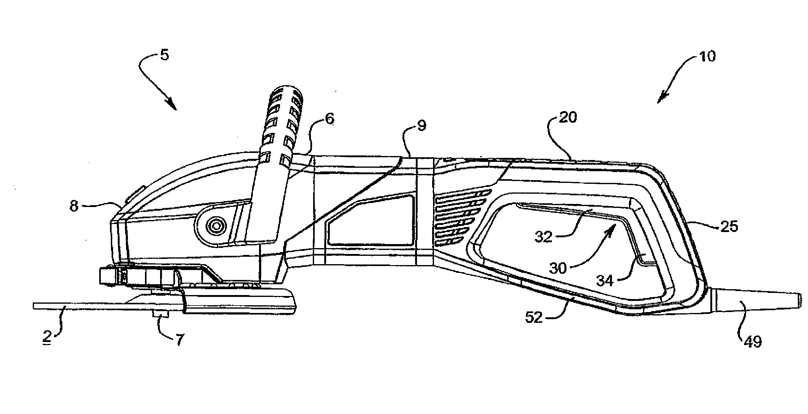
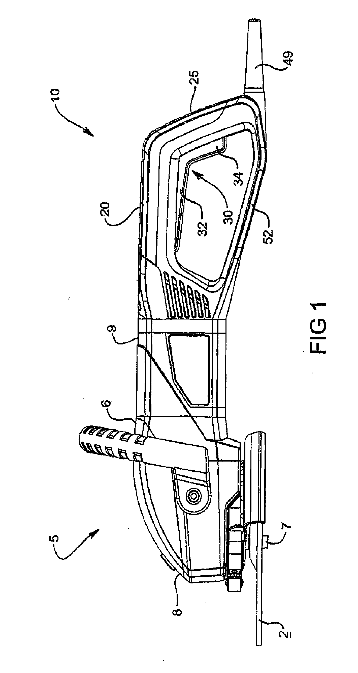
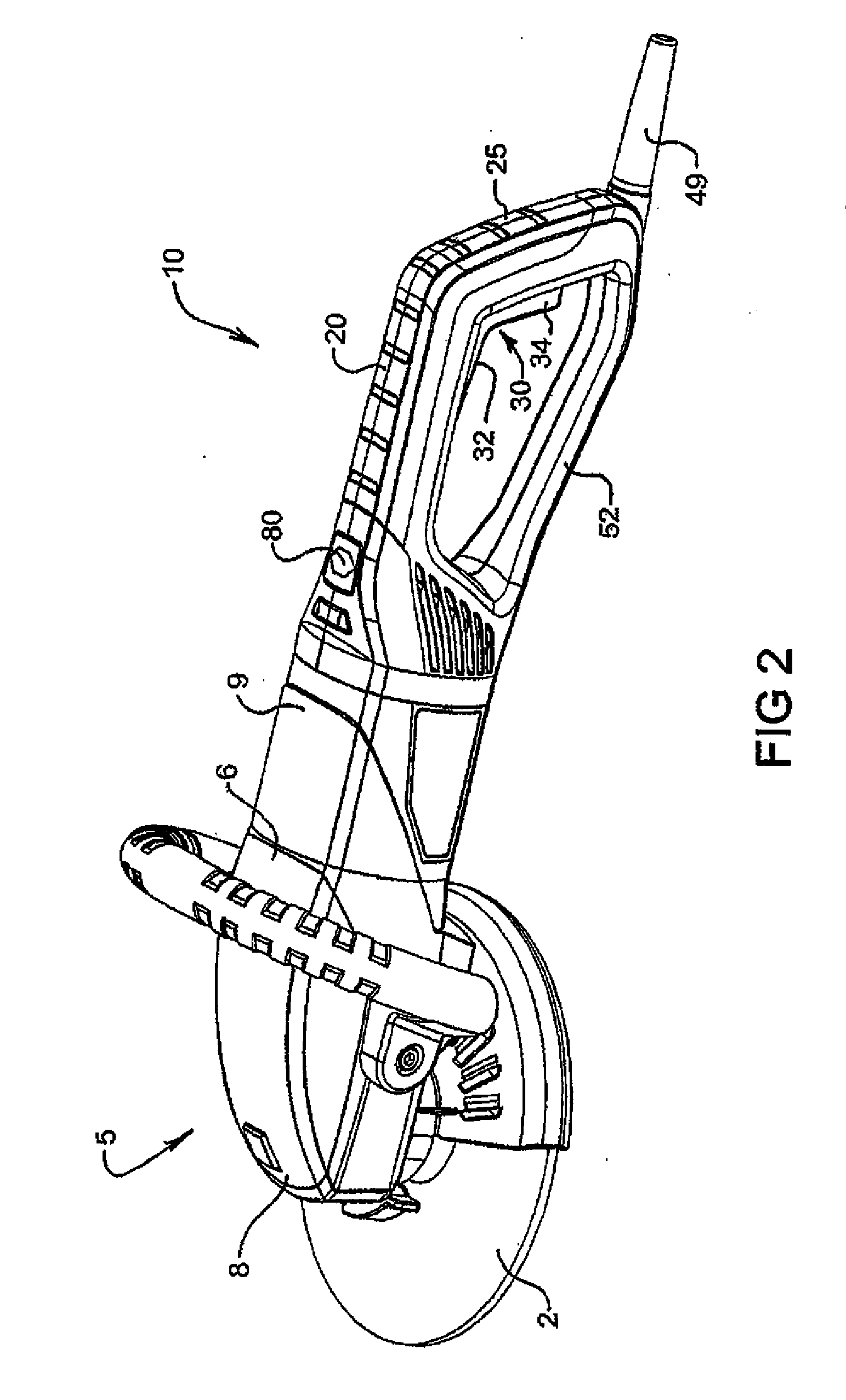
[0010]Accordingly, in a first aspect the present invention is directed towards providing a handle assembly for a hand held power tool, the assembly including:

[0011]first and second handle portions for gripping the power tool, the first handle portion extending substantially transverse to the second handle portion;

[0012]a trigger including an elongate portion associated with the first handle portion and a flange portion associated with the second handle portion; and

[0013]a switch for operating the power tool actuated by movement of either the elongate portion or the flange portion relative to the first or second handle portions respectively.

[0014]An advantage of the invention over existing gripping means and switch assemblies for holding and operating hand held power tools is that a user can grip and operate a device incorporating the invention more easily, more securely, with more control and with less discomfort. Another advantage is that a user need not grip the housing of such a ...


PUM

PropertyMeasurementUnit
Angleaaaaaaaaaa
Angleaaaaaaaaaa
Angleaaaaaaaaaa

Abstract

A handle assembly for a power tool, such as an angle grinder, including first and second handle portions for gripping the power tool, the first handle portion extending substantially transverse to the second handle portion. The handle assembly also having a trigger including an elongate portion associated with the first handle portion and a flange portion associated with the second handle portion and a switch for operating the power tool actuated by movement of either the elongate or flange portion of the trigger relative to the first or second handle portions respectively.

Description

CROSS REFERENCE TO RELATED APPLICATIONS[0001]This application is a continuation-in-part application of PCT Application No. PCT / AU2007 / 000537, filed Apr. 26, 2007, which claims priority to AU 2006902154, filed Apr. 26, 2006, both of which are incorporated herein by reference in their entirety.BRIEF DESCRIPTION OF THE INVENTION[0002]The present invention relates to power hand tools and more particularly to a handle assembly of the type used for holding, activating and deactivating a power hand tool. The handle assembly of the present invention is particularly suitable for use in relation to a hand held power angle grinder and is discussed below in this context.BACKGROUND OF THE INVENTION[0003]Hand held power angle grinders have an electric motor driving a driven member that grips a working element, such as an abrasive disc, for performing work on a workpiece. There are a myriad of different discs that are used for various materials and tasks, such as cutting discs, buffing pads and sa...

Claims


Application Information

Patent Timeline
IPC IPC(8): B24B27/08B23B45/00
CPCB25F5/02G05G5/06G05G1/06G05G1/02
Inventor VAN DER LINDE, BENJAMIN LUKESCRIMSHAW, DAVID LEIGHDAVIES, PAULMILLER, PAULCONNOR, PAUL FRANCIS
Owner DEMAIN TECH
Why Eureka
Try Eureka