Microcomputer system

a microcomputer and system technology, applied in the field of microcomputer systems, can solve problems such as difficulty in reducing power consumption, and achieve the effect of reducing power consumption

Inactive Publication Date: 2009-04-23
DENSO CORP
View PDF3 Cites 19 Cited by
  • Summary
  • Abstract
  • Description
  • Claims
  • Application Information

AI Technical Summary

Benefits of technology

[0006]The present invention has therefore an object to provide a microcomputer system, which appropriately controls the supply of power to a main CPU section so as to reduce the power consumption.

Problems solved by technology

For this reason, even if only the supply of the clock signal to the CPU stops, it is difficult to reduce the power consumption because of the leak current (off leak).

Method used


Image

  • Microcomputer system
  • Microcomputer system
  • Microcomputer system

Examples


first embodiment

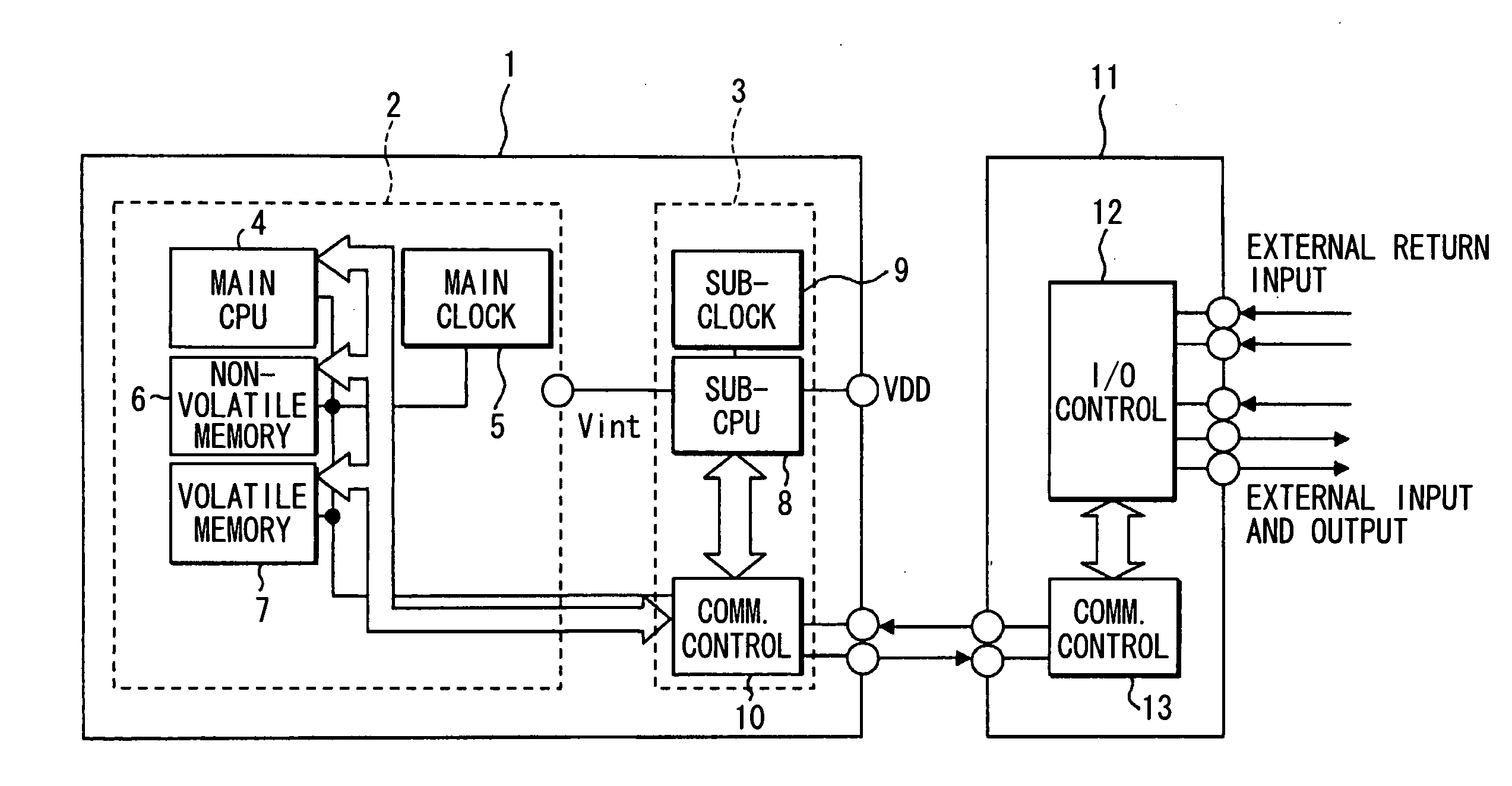
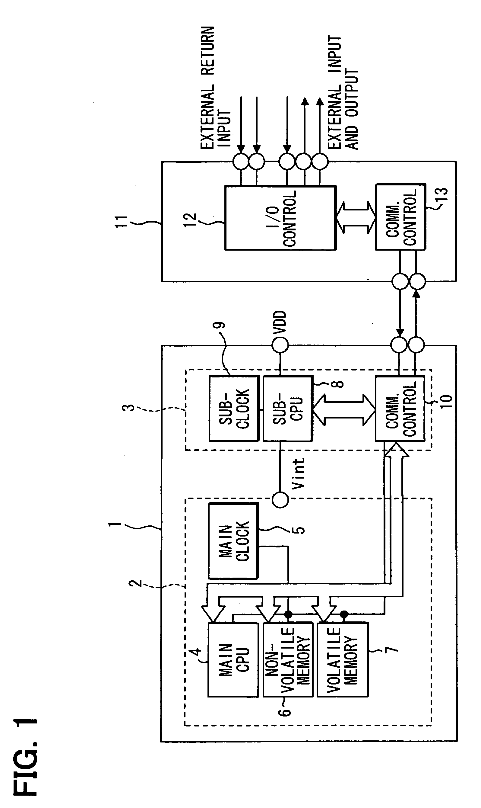
[0025]Referring first to FIG. 1, a microcomputer system 1 is applied for the electronic control of, for example, an in-vehicle device (not shown). The microcomputer system 1 includes a main microcomputer (main MC or main CPU section) 2, and a sub-microcomputer (sub-MC or sub-CPU section) 3.

[0026]The main microcomputer 2 includes a main CPU 4, a main clock section 5, a (main) nonvolatile memory element 6, and a (main) volatile memory element 7. The main CPU 4 operates in response to a main clock signal having a frequency of, for example, about 100 MHz, which is supplied from the main clock section 5. The main CPU 4 is, for example, a 32-bit CPU, and executes a main portion of the processing in the microcomputer system 1. The main clock section 5 multiplies a reference clock signal that is output from an oscillator circuit having an external oscillator by a multiplier circuit although being not specifically shown, to generate a main clock signal.

[0027]The nonvolatile memory element 6 ...

second embodiment

[0062]Referring to FIG. 8, a microcomputer system 31 according to a second embodiment includes a main microcomputer (main MC or main CPU section) 32, a sub-microcomputer (sub-MC or sub-CPU section) 33, and a memory element section 34. The memory element section 34 is formed of a chip that makes the memory elements 6 and 7 separately from the main microcomputer 3. Those memory elements 6 and 7 are mounted on the main microcomputer 3 in the first embodiment. The memory element section 34 can be accessed from both of the main microcomputer 32 side and the sub-microcomputer 33 side.

[0063]The main microcomputer 32 includes a main CPU 35 and logic circuits 36 (36A to 36D, for example, gate array) which are peripheral circuits. Those logic circuits 36 also operate upon receiving the main clock signal.

[0064]The sub-microcomputer 33 includes a sub-CPU 37, a communication control section 38 and a power supply control section (power supply control circuit) 39. The sub-microcomputer 33 also inc...


PUM


Abstract

A sub-microcomputer having a sub-CPU and a power supply control section that controls the power supply to a main microcomputer is disposed in addition to the main microcomputer having a main CPU. A sub-clock section that supplies a sub-clock signal having a lower frequency to the sub-microcomputer can change over between a continuous mode and an intermittent mode. When the main CPU gives an operation stop notification to the sub-CPU, the sub-CPU recognizes the notification, stops the power supply to the main microcomputer, and sets the sub-clock section to the intermittent mode. The sub-CPU determines that the operation state condition is satisfied in the period of the intermittent mode, the sub-CPU changes over the sub-clock section to the continuous mode to restart the power supply to the main microcomputer.

Description

CROSS REFERENCE TO RELATED APPLICATION[0001]This application is based on and incorporates herein by reference whole contents of Japanese Patent Applications No. 2007-272256 filed on Oct. 19, 2007 and No. 2008-145773 filed on Jun. 3, 2008.FIELD OF THE INVENTION[0002]The present invention relates to a microcomputer system having a configuration section that operates by supply of a sub-clock signal having a frequency lower than that of a main clock signal which is supplied to the a main CPU section to control the operation of the main CPU section.BACKGROUND OF THE INVENTION[0003]In a conventional microcomputer system, in order to reduce power consumption, a microcomputer is shifted to a sleep mode that stops the supply of operation clock to hold the internal state when the microcomputer becomes a state in which an event to be processed does not occur. For example, U.S. Pat. No. 5,737,588 (JP 8-76873A) discloses that the operation of a main oscillator circuit that supplies a clock signa...

Claims


Application Information

Patent Timeline
Patent Type & Authority Applications(United States)
IPC IPC(8): G06F1/08
CPCG06F1/3203G06F1/324Y02B60/1217Y02B60/121G06F1/3293Y02D10/00
Inventor TAGUCHI, SHINICHIROUYAMADA, KENJIINOUE, AKIMITSUISHIHARA, HIDEAKI
Owner DENSO CORP
Why Eureka
Try Eureka