Engine speed sensitive oil pressure regulator

a technology of oil pressure regulator and engine, which is applied in the direction of machine/engine, engine revolution, lubrication of auxillaries, etc., can solve the problems of overspeed condition, insufficient lubrication, and inability to manually adjust the maximum allowable oil pressure during operation, so as to reduce the pressure, and reduce the pressure in the pressurized fluid line

Active Publication Date: 2009-04-30
CATERPILLAR INC
View PDF1 Cites 13 Cited by
  • Summary
  • Abstract
  • Description
  • Claims
  • Application Information

AI Technical Summary

Benefits of technology

[0008]In one aspect, the presently disclosed embodiments may be directed to a pressure regulator for a power source. The pressure regulator may include a housing in fluid communication with a pressurized fluid line and a reservoir. The pressure regulator may also include a pressure relief valve in the housing having an open position that creates a flow path between the pressurized fluid line and the reservoir, and a closed position. The pressure relief valve may be configured to open when an opening force exerted on the pressure relief valve by pressurized fluid entering the housing overcomes a closing force acting on the pressure relief valve, allowing pressurized fluid to flow from the pressurized fluid line to the reservoir to reduce pressure in the pressurized fluid line. The pressure regulator may further include a governor coupled to the pressure relief valve. The governor may be configured to regulate the pressure in the pressurized fluid line by selectively adjusting the closing force exerted on the pressure relief valve based on engine speed.
[0009]In another aspect, the presently disclosed embodiments may be directed to a method of regulating pressure in a pressurized fluid line of an engine assembly. The method may include coupling a pressure relief valve to the pressurized fluid line. The pressure relief valve may have an open position for reducing pressure in the pressurized fuel line, and a closed position. The method may also include exerting a closing force on the pressure relief valve using a biasing mechanism. The method may further include exerting an opening force on the pressure relief valve using the pressure in the pressurized fluid line. The pressure relief valve may open when the opening force exceeds the closing force. The method may further include regulating the pressure in the pressurized fluid line by selectively adjusting with a governor the amount of opening force required to open the pressure relief valve based on engine speed.
[0010]In yet another aspect, the presently disclosed embodiments may be directed to a power system including an engine assembly. The power system may also include a pressure regulator for the engine assembly. The pressure regulator may include a housing having a first opening fluidly coupled to a pressurized fluid line, a second opening fluidly coupled to the pressurized fluid line, and a third opening fluidly coupled to a reservoir. The pressure regulator may also include a pressure relief valve in the housing having an open position that creates a flow path between the first opening and the third opening, and a closed position. The pressure relief valve may be configured to open when an opening force exerted on the pressure relief valve by pressurized fluid entering the second opening overcomes a closing force acting on the pressure relief valve, allowing pressurized fluid to flow from the pressurized fluid line to the reservoir to reduce pressure in the pressurized fluid line. The pressure regulator may also include a governor coupled to the pressure relief valve. The governor may be configured to regulate the pressure in the pressurized fluid line by selectively adjusting the closing force exerted on the pressure relief valve based on engine speed.

Problems solved by technology

Due to the location of the pressure regulator on the engine, manually adjusting the maximum allowable oil pressure during operation may not be practical.
An overspeed condition may result from an operation such as engine braking on a steep grade.
Because the engine speed during an overspeed condition may be much higher than at the maximum engine operating speed, the maximum allowable pressure setting of the pressure regulator may not be high enough to provide sufficient lubrication at overspeed conditions, if the maximum pressure was set to correspond to the maximum pressure required at a lower operating speed.
Although the system disclosed in the '479 patent may allow a higher maximum oil pressure as engine speeds increase, it may be complex and costly.
The additional components increase the control difficulty and expense of the system.
The additional components also preclude the retrofit of an oil pressure regulation system on engines that do not include an ECU.

Method used


Image

  • Engine speed sensitive oil pressure regulator
  • Engine speed sensitive oil pressure regulator
  • Engine speed sensitive oil pressure regulator

Examples


Embodiment Construction

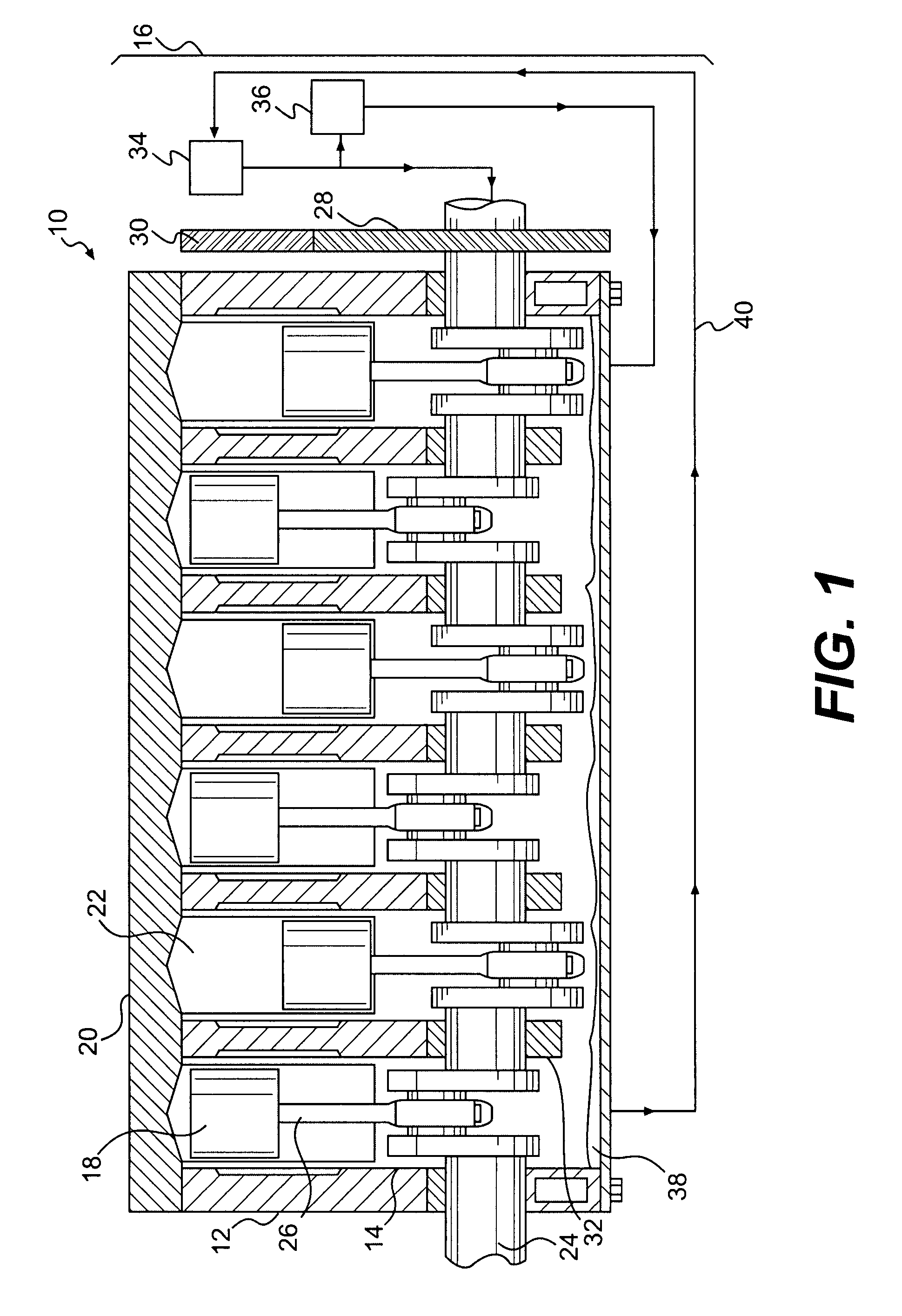
[0013]FIG. 1 illustrates an exemplary embodiment of a power source 10. For the purposes of this disclosure, power source 10 is depicted and described as a four-stroke engine. One skilled in the art will recognize that power source 10 may embody any type of internal combustion engine such as, for example, a heavy fuel engine, a diesel engine, a gasoline engine, a gaseous fuel-powered engine, or any other suitable engine. Power source 10 may be configured to cooperate with a drive train (not shown) to provide motive power to a machine or vehicle (not shown). Power source 10 may further be configured to cooperate with the drive train to provide compression braking to slow the machine or vehicle. Power source 10 may have maximum operating speed, or redline speed, which is the maximum sustained speed at which power source 10 may safely and reliably operate to provide power or compression braking. Power source 10 may also be capable of operating in a overspeed condition for short periods ...


PUM


Abstract

A pressure regulator for a power source may include a housing in fluid communication with a pressurized fluid line and a reservoir, and a pressure relief valve having an open position that creates a flow path between the pressurized fluid line and the reservoir, and a closed position. The pressure relief valve may open when an opening force exerted by pressurized fluid entering the housing overcomes a closing force acting on the pressure relief valve, allowing pressurized fluid to flow from the pressurized fluid line to the reservoir. The pressure regulator may also include a governor coupled to the pressure relief valve, wherein the governor is configured to regulate the pressure in the pressurized fluid line by selectively adjusting the closing force exerted on the pressure relief valve based on engine speed.

Description

TECHNICAL FIELD [0001]The present disclosure relates to a pressure regulator, and, more particularly, to an engine speed sensitive oil pressure regulator for an internal combustion engine.BACKGROUND[0002]Internal combustion engines such as, for example, gasoline engines, diesel engines, and gaseous fuel powered engines, contain internal moving parts that rely on a pressurized fluid for proper lubrication. The fluid is often a high-viscosity oil, which is introduced between moving parts to create a thin, protective layer of oil, allowing the parts to be separated, thereby reducing friction and wear. A pump draws the fluid from a reservoir and pressurizes it, causing it to flow through passageways in the engine to moving parts that require lubrication. The pressure of the fluid is regulated by a pressure relief valve consisting of a spring-loaded spool, which relieves the fluid pressure by moving the spool against the spring to create a relief passage for the fluid when the pressure r...

Claims


Application Information

Patent Timeline
Patent Type & Authority Applications(United States)
IPC IPC(8): F01M11/02
CPCF01M2250/64F01M1/16
Inventor BOCHART, MICHAEL R.
Owner CATERPILLAR INC
Why Eureka
Try Eureka