Engine idle speed and turbocharger speed control

Active Publication Date: 2009-04-30
FORD GLOBAL TECH LLC
View PDF8 Cites 28 Cited by
  • Summary
  • Abstract
  • Description
  • Claims
  • Application Information

AI Technical Summary

Benefits of technology

[0005]In this way, the turbocharger speed may be selectively maintained responsive to the driver's actions, which can indicate a likely intent to tip-in, for example, where turbo lag should be

Problems solved by technology

Specifically, the late injection generates exhaust heat, which in turn increases the speed of the turbine.
However, the inventors herein have recognized some issues with the above approach.
In particular, in gasoline applications,

Method used


Image

  • Engine idle speed and turbocharger speed control
  • Engine idle speed and turbocharger speed control
  • Engine idle speed and turbocharger speed control

Examples


Embodiment Construction

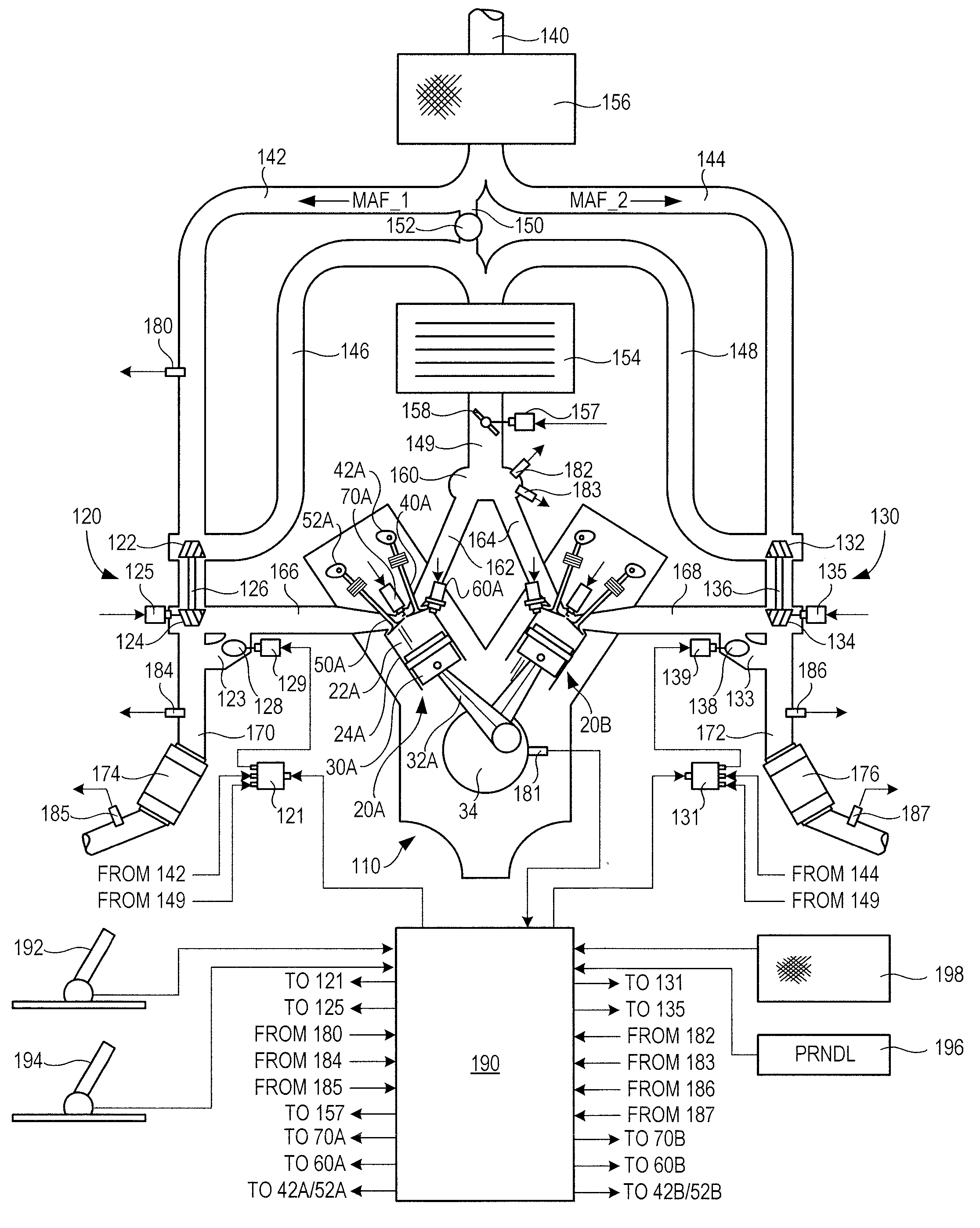
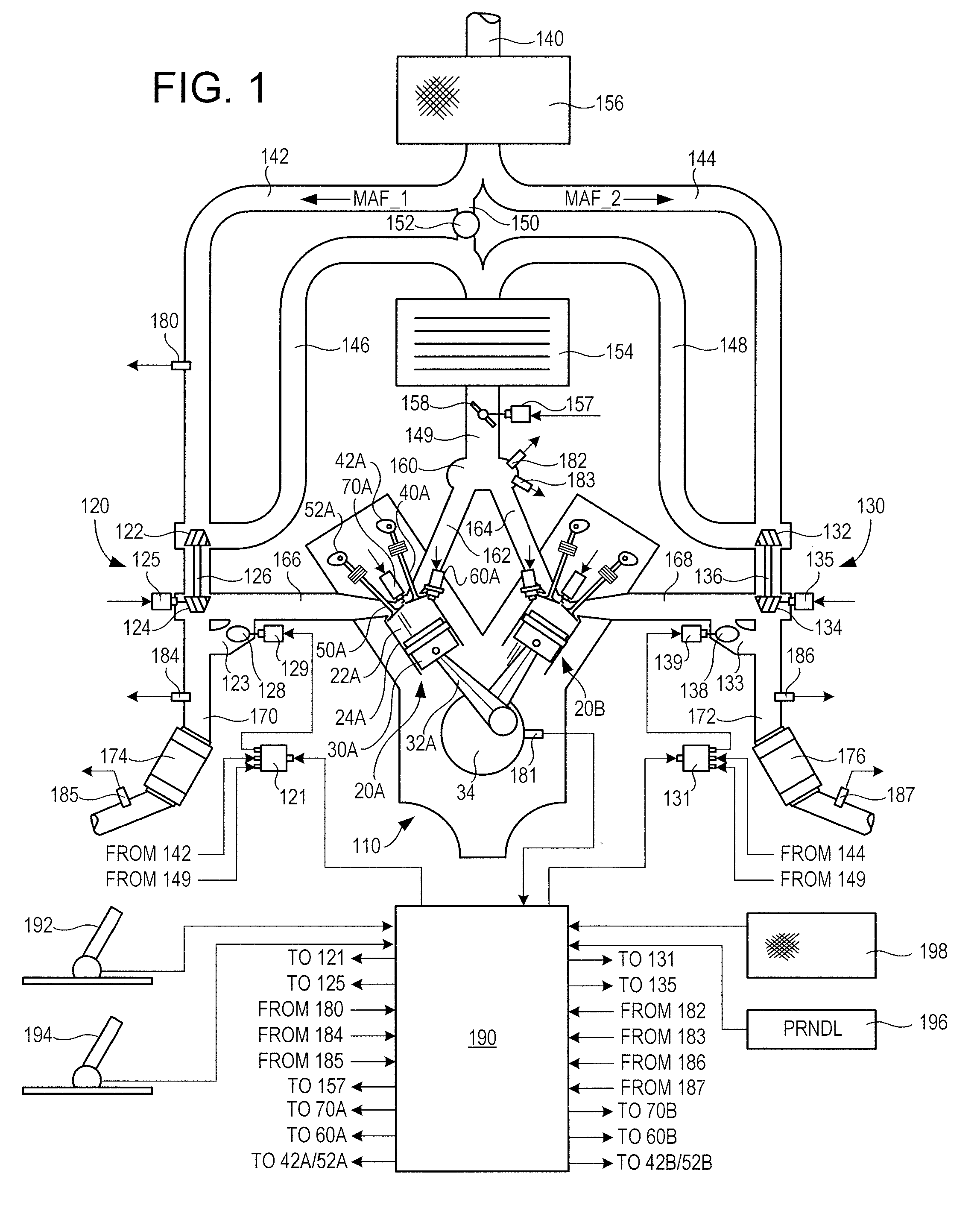
[0010]FIG. 1 shows a schematic depiction of an example engine system 100 including a multi-cylinder internal combustion engine 110 and twin turbochargers 120 and 130. As one non-limiting example, engine system 100 can be included as part of a propulsion system for a passenger vehicle. Also, while this example shows a twin turbocharger example, a single turbocharger, or more than two turbines and / or compressors may be used.

[0011]Engine system 100 can receive intake air via intake passage 140. Intake passage 140 can include an air filter 156. At least a portion of the intake air can be directed to a compression device or compressor 122 of turbocharger 120 via a first branch of the intake passage 140 as indicated at 142 and at least a portion of the intake air can be directed to a compressor 132 of turbocharger 130 via a second branch of the intake passage 140 as indicated at 144.

[0012]A first portion of the total intake air can be compressed via compressor 122 where it may be supplied...


PUM


Abstract

Various methods are described for controlling engine operation for an engine having a turbocharger and direction injection. One example method includes performing at least a first and second injection in response to a driver action. The first and second injection may be performed during a cylinder cycle, the first injection generating a lean combustion and the second injection injected after combustion such that it exits the cylinder unburned into the exhaust upstream of a turbine of the turbocharger.

Description

BACKGROUND AND SUMMARY[0001]Engines may utilize turbocharging to increase power density and / or increase engine fuel efficiency. However, during transient conditions, such as a driver request for increased engine output, turbocharger inertia and flow dynamics may result in “turbo lag.” Such lag may be reduced in some examples by reducing turbocharger size and weight, and / or taking various measures via engine control.[0002]One control approach to address turbo lag uses a late fuel injection into lean diesel combustion to generate exhaust heat, thereby maintaining spin-up of the turbine of the turbocharger. Specifically, the late injection generates exhaust heat, which in turn increases the speed of the turbine. Then, when a transient occurs, such as a request for an increase in engine output, the turbine is already spinning fast enough to provide the rapid increase in engine output.[0003]However, the inventors herein have recognized some issues with the above approach. In particular, ...

Claims


Application Information

Patent Timeline
IPC IPC(8): F02B3/00
CPCF02D37/02F02D41/0007F02D41/08Y02T10/144F02D2250/22Y02T10/44F02D41/405Y02T10/12Y02T10/40
Inventor PALLETT, TOBIAS JOHNSURNILLA, GOPICHANDRA
Owner FORD GLOBAL TECH LLC
Why Eureka
Try Eureka