Low shock strength inlet

a shock strength and low-pass filter technology, applied in the direction of machines/engines, combustion air/fuel air treatment, composite engine plants, etc., can solve the problems of reducing the efficiency of inlet pressure recovery and flow pumping, complex inlet design with high drag, and affecting the flow stability of the diffuser

Active Publication Date: 2009-04-30
GULFSTREAM AEROSPACE CORP
View PDF99 Cites 44 Cited by
  • Summary
  • Abstract
  • Description
  • Claims
  • Application Information

AI Technical Summary

Benefits of technology

[0011]In accordance with one embodiment of the invention, a supersonic inlet may include a leading edge configured to generate a first shock wave, a compression surface positioned downstream of the leading edge, and a cowl lip spatially separated from the compression surface such that the cowl lip and the compression surface define an inlet opening for receiving a supersonic flow. The supersonic inlet may also include a bypass splitter disposed between the cowl lip an

Problems solved by technology

This traditional approach, however, often results in a complex inlet design with high drag.
If this is not done, a complex internal shock structure and an adverse subsonic diffuser flow area profile may result, possibly reducing the inlet pressure recovery and flow pumping efficiency, as well as undermining diffuser flow stability.
As mentioned, when the supersonic design speed increases, the amount of compression needed to decelerate the flow to a fixed terminal shock Mach number also increases, resulting in an increase in cowl lip angle.
Any increase in cowl lip angle results in additional inlet frontal area, which increases inlet drag as speed increases.
This adverse trend is a key reason why conventional external compression inlets lose viability at high supersonic Mach numbers.
Problems with this method include the aircraft integration challenges created by the 3-D geometry, such as the fact that the cross-sectional shape may be more diffi

Method used


Image

  • Low shock strength inlet
  • Low shock strength inlet
  • Low shock strength inlet

Examples


Embodiment Construction

[0019]The present disclosure will now be described more fully with reference to the Figures in which various embodiments of the invention are shown. The subject matter of this disclosure may, however, be embodied in many different forms and should not be construed as being limited to the embodiments set forth herein.

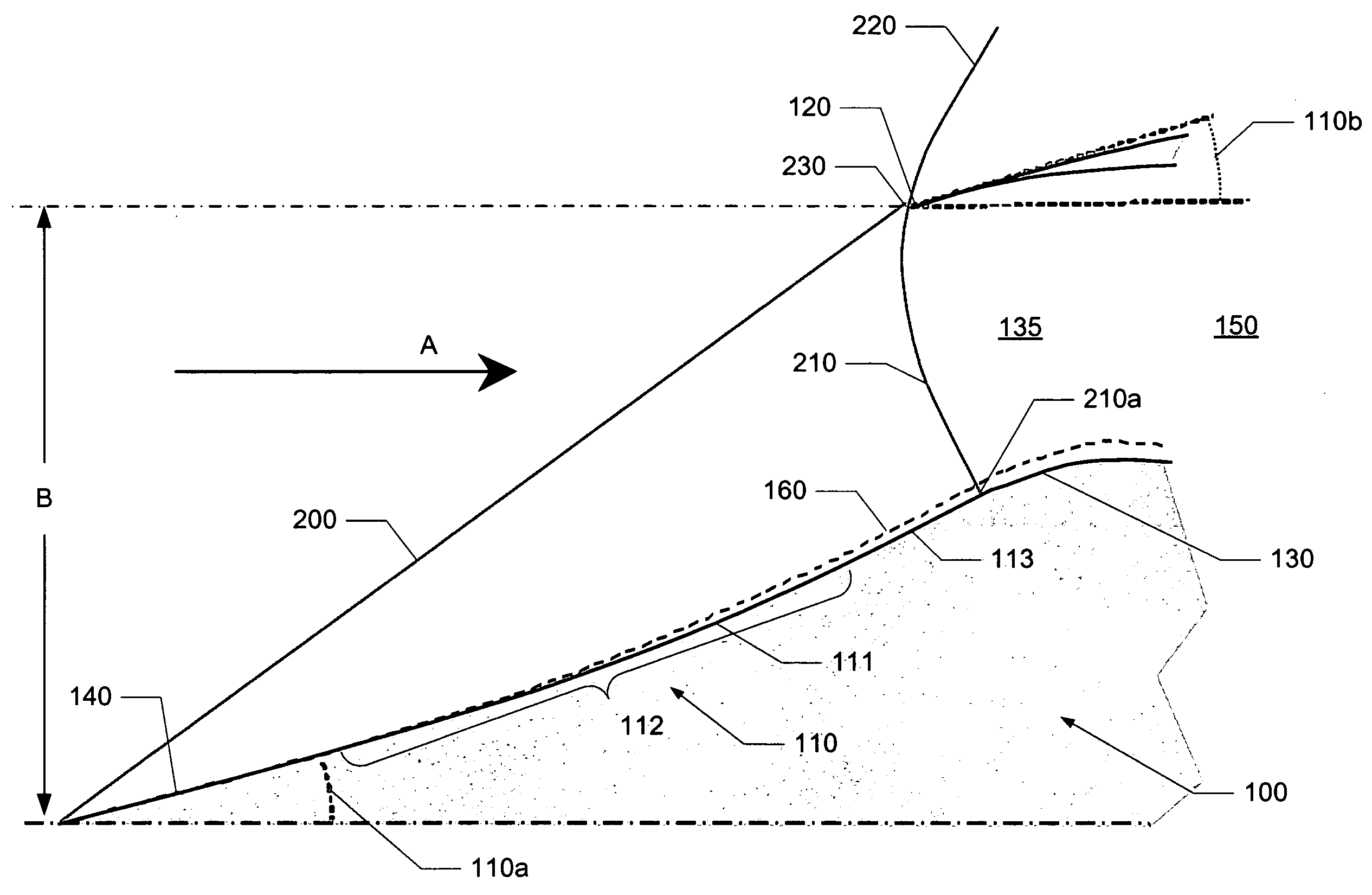
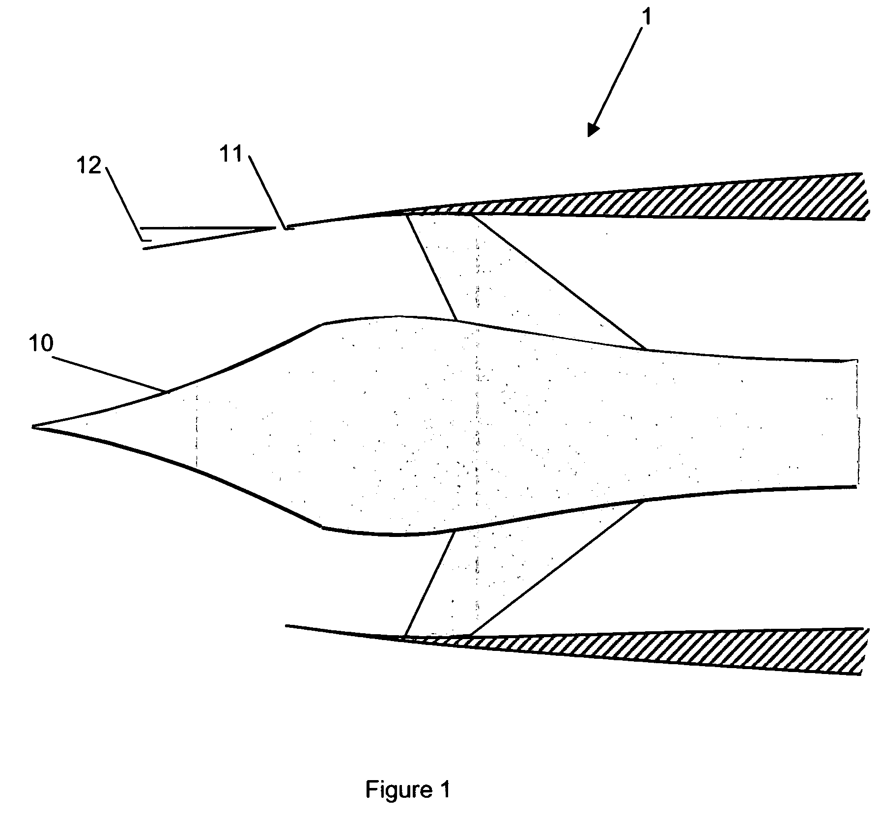
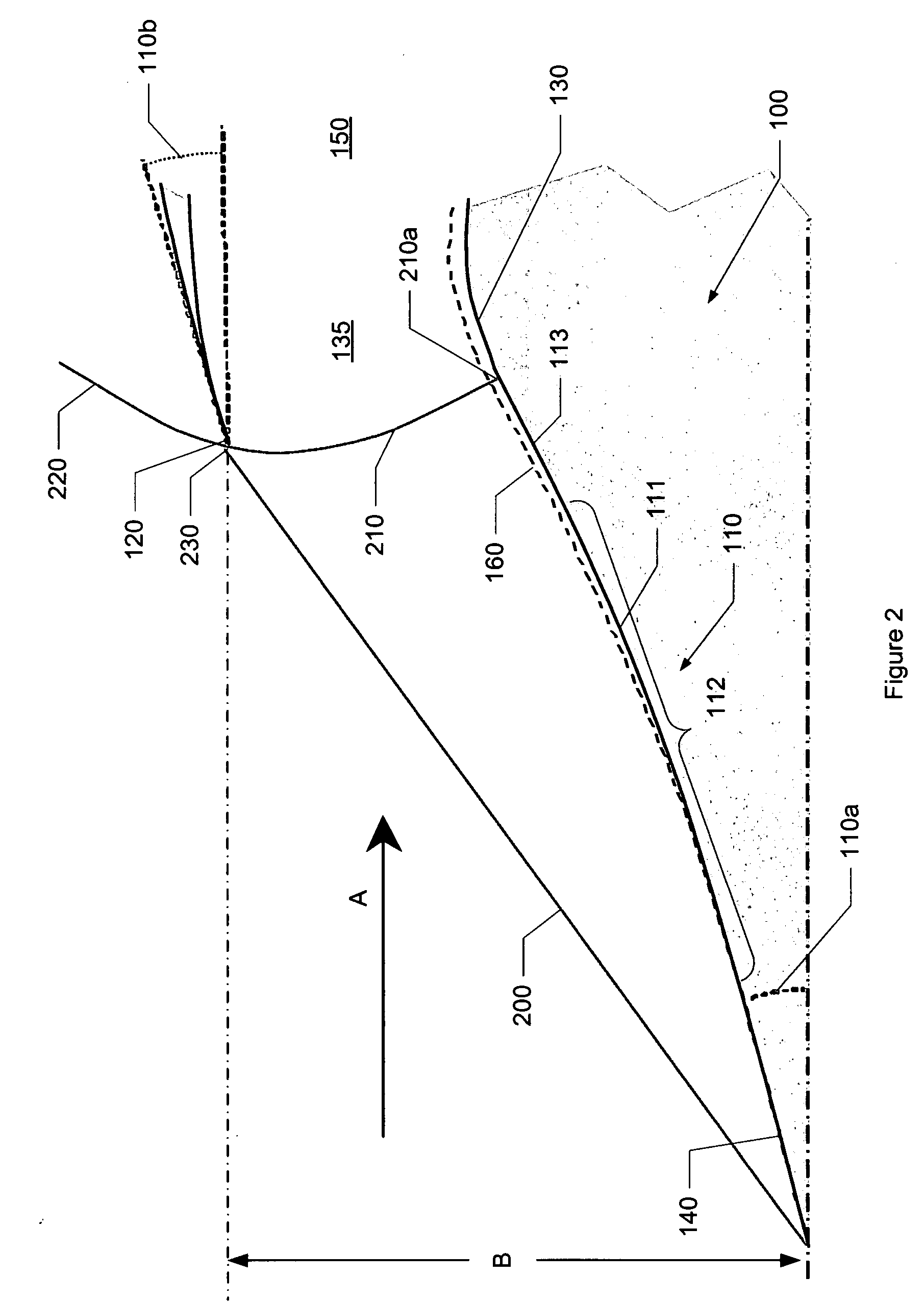
[0020]An embodiment of the invention may include a supersonic inlet for supersonic aircraft that is configured to reduce the inlet's contribution to a supersonic aircraft's sonic boom signature. To accomplish this, embodiments of the invention may position the cowl lip of the inlet such that the inlet captures the initial conic and / or oblique shock within the intake plane, preventing the conic shock energy or discontinuity from merging with the shocks generated by the airframe during supersonic flight. It is also contemplated that the cowl angle of the nacelle may be reduced to zero or substantially zero in order to reduce the contribution of cowl shock and cowl drag on ...


PUM


Abstract

Embodiments of the invention relate to a supersonic inlet having a cowl lip configured to capture the conic shock and exhibit a zero or substantially zero cowl angle. The inlet may be configured to employ a relaxed isentropic compression surface and an internal bypass. The nacelle bypass may prevent flow distortions, introduced by the capture of the conic shock, from reaching the turbomachinery, thereby allowing the cowl angle to be reduced to zero or substantially zero. Such a cowl angle may reduce the inlet's contribution to the overall sonic boom signature for a supersonic aircraft while allowing for an increase in engine pressure recovery and a subsequent improvement in generated thrust by the engine.

Description

[0001]This application claims priority to co-pending U.S. Provisional Patent Application 60 / 960,986, filed Oct. 24, 2007, and entitled “Supersonic Nacelle,” which is hereby incorporated by reference in its entirety.FIELD OF INVENTION[0002]The embodiments of the present invention relate generally to supersonic inlets for supersonic aircraft and more particularly to supersonic inlets configured to reduce the supersonic inlet's contribution to the aircraft's sonic boom signature.BACKGROUND OF THE INVENTION[0003]Gas turbine engines can propel aircraft at supersonic speeds. However, the gas turbine engines generally operate on subsonic air flow in the range of about Mach 0.3 to 0.6 at the upstream face of an engine. The inlet of the engine functions to decelerate the incoming airflow to a speed compatible with the requirements of the gas turbine engine. In order to do this, the inlet has a compression surface and a corresponding flow path, used to decelerate the supersonic flow into a st...

Claims


Application Information

Patent Timeline
IPC IPC(8): F02C7/04
CPCB64D33/02B64D2033/026F02C7/042Y02T50/672F02C7/045F05D2220/80F02K7/16Y10T137/0536Y10T137/0368F02K3/025Y02T50/60B64D29/00B64D33/06B64D2033/0273
Inventor CONNERS, TIMOTHY R.
Owner GULFSTREAM AEROSPACE CORP
Why Eureka
Try Eureka