Arc welding robot control system and method thereof

a control system and arc welding technology, applied in the direction of welding equipment, gripping heads, manufacturing tools, etc., can solve the problems of deviating welding bead thickness, deviating welding wire, deviating from the desired welding line, etc., to prevent the thickness of welding bead deviation, accurate arc welding, and reduce the influence of delay

Active Publication Date: 2009-04-30
KOBE STEEL LTD
View PDF9 Cites 20 Cited by
  • Summary
  • Abstract
  • Description
  • Claims
  • Application Information

AI Technical Summary

Benefits of technology

[0007]Accordingly, it is an object of the present invention to provide an arc welding robot control system, a method thereof and a program thereof that prevent the thickness of welding bead from becoming deviated even in the case in which an arc welding robot performs a weaving operation, and solve the problems described above.
[0009]With this configuration, the arc welding robot control system changes welding conditions of an arc welding robot every time when a welding torch completes to perform one weaving cycle, based on to-be-changed welding conditions at a travelling position, while the welding torch of the arc welding robot is positioned between a welding condition changing start point and a welding condition changing finish point. The arc welding robot control system therefore does not change the welding conditions during the welding torch is performing one cycle of weaving operation. Here, the arc welding robot control system is able to set a welding condition changing start point, a welding condition changing finish point, welding conditions at the welding condition changing start point, and welding conditions at the welding condition changing finish point freely depending on a shape of welding groove, and a shape, material and size of each work piece.
[0011]With this configuration, the arc welding robot control system allows the welding condition changing device to change welding conditions when the welding torch arrived at the center of welding line, after being delayed for a delay time by the weaving operation delay-time adjusting device, the delay time being due to a filtering delay, a mechanical delay, or the like. Normally, the faster the weaving cycle becomes, the larger the influence of a delay becomes, but even in such a case, this arc welding robot control system can reduce the influence of such a delay.
[0014]According to an arc welding robot control system and a method thereof according to the present invention, the following excellent effects can be provided. That is, even in the case in which an arc welding robot performs a weaving operation, since welding conditions are changed every time when its welding torch completes one weaving cycle, it is prevented that the thickness of welding bead becomes deviated. Moreover, according to a system further including a weaving operation delay-time adjusting device, even in the case in which a fast weaving cycle is performed, it is possible to prevent the thickness of welding bead to become deviated and to reduce the influence of a delay; thereby it becomes possible to perform an accurate arc welding.

Problems solved by technology

In the prior arts disclosed in the above two patent documents, welding conditions are changed while a welding torch performs one cycle of weaving operation and command values of welding currents at both left and right ends of the weaving operation become different to each other, which causes a problem that the thickness of welding bead becomes deviated.
In addition, even in the case that an arc welding robot is provided with an arc sensor, since actual values of welding currents at both left and right ends of the weaving operation are different to each other, its welding wire fails to follow a desired welding line and deviates therefrom.
Furthermore, an actual weaving operation of a welding torch delays a bit with respect to the commanded weaving operation, and due to the delay the timing when the welding torch completes one weaving cycle and the timing when welding conditions such as a welding current and the like are actually changed deviate from each other, so welding currents at both left and right ends of the weaving operation do not agree with each other; the faster the weaving cycle becomes, the larger the thickness of welding bead becomes deviated.

Method used


Image

  • Arc welding robot control system and method thereof
  • Arc welding robot control system and method thereof
  • Arc welding robot control system and method thereof

Examples


Embodiment Construction

1. Overview of the Control System

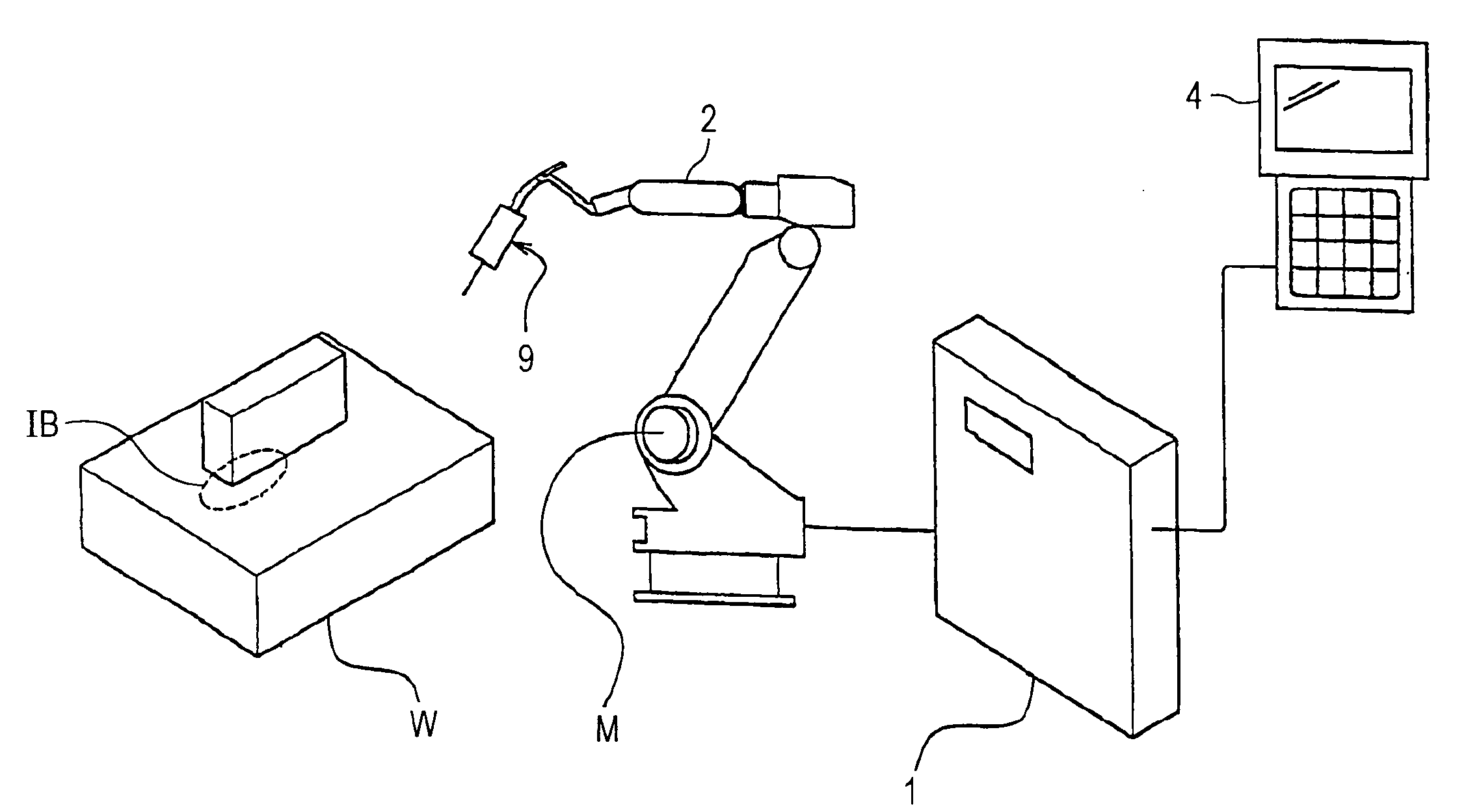
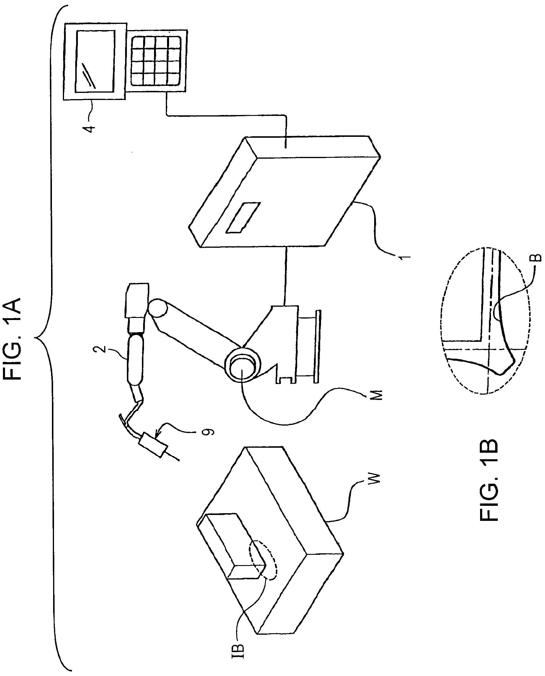
[0027]An embodiment of the present invention will now be described below in detail with reference to the attached drawings. First, a configuration outline of a control system will be described with reference to FIGS. 1A, 1B. FIG. 1A is a schematic overview of an arc welding system including a control system according to the present invention, and FIG. 1B is a magnified view of work pieces and a welding bead which are denoted with the mark “IB” in FIG. 1A. In FIG. 1A, there are shown a control system (an arc welding robot control system) 1, an arc welding robot 2, a teaching pendant 4, a welding torch 9 and work pieces W; the work pieces W and a welding bead B are also shown in FIG. 1B.

[0028]A control system 1 connected to an arc welding robot 2 and a teaching pendant 4 serves to control the arc welding robot 2 and to change welding conditions of the arc welding robot 2 based on a command or a teaching program, which is input from the teaching pendant...


PUM

PropertyMeasurementUnit
distanceaaaaaaaaaa
distanceaaaaaaaaaa
speedaaaaaaaaaa

Abstract

An arc welding robot control system of the present invention includes memory devices, controlling devices, a welding condition changing position calculating device, a weaving operation controlling device that outputs a signal of completion of one weaving cycle every time when a welding torch completes to perform one weaving cycle of a predetermined movement pattern, a welding condition calculating device for calculating to-be-changed welding conditions, and a welding condition changing device that changes welding conditions of an arc welding robot, based on to-be-changed welding conditions, every time when a signal of completion of one weaving cycle is input. With this configuration, it enables a continuous change of welding conditions and a copying arc welding with high accuracy even in the case in which the arc welding robot performs a weaving operation.

Description

BACKGROUND OF THE INVENTION[0001]1. Field of the Invention[0002]The present invention relates to an arc welding robot control system continuously changing welding conditions of an arc welding robot.[0003]2. Description of the Related Art[0004]Hitherto, in arc welding using an arc welding robot, in order to change welding conditions such as a welding current, a welding voltage, a welding speed, a weaving cycle, a weaving amplitude, and the like in stages, it has been required to specify (teach) a plurality of welding-condition changing positions (teaching positions) and to set such welding conditions, which vary from one welding-condition changing position to another, by hand. Since it is so complicated to change welding conditions by hand at every position where welding conditions need to be changed, there have been developed some techniques for changing welding conditions automatically (refer to Japanese Unexamined Utility Model Registration Publication No. S61-138470 and U.S. Pat....

Claims


Application Information

Patent Timeline
Patent Type & Authority Applications(United States)
IPC IPC(8): B23K9/12
CPCB23K9/0953B23K9/0216B23K9/12B25J13/00B25J15/0066
Inventor ASAI, AKIHIKOSHIGEYOSHI, MASAYUKI
Owner KOBE STEEL LTD
Why Eureka
Try Eureka