Sheet material feeding apparatus

a feeding apparatus and sheet material technology, applied in the direction of metal working apparatus, thin material handling, article separation, etc., can solve the problems of easy degradation of accuracy for a feeding length, and difficulty in preventing flexure and winding of sheet material round a roll. achieve the effect of stable feeding of sheet material

Active Publication Date: 2009-04-30
SANKYO SEISAKUSHO
View PDF10 Cites 4 Cited by
  • Summary
  • Abstract
  • Description
  • Claims
  • Application Information

AI Technical Summary

Benefits of technology

[0013]A construction is preferable, in which the other of the pair of rolls, which cooperates with the one of the pair of rolls, has a plurality of circumferential grooves arranged between both ends of a sheet material feeding surface in an axial direction and spaced from one another in the axial direction, the second guide member includes guide portions passing through the plurality of circumferential grooves on the other of the pair of rolls and extending continuously to a downstream sid

Problems solved by technology

Also, since a pair of rolls interpose therebetween the sheet material with a sufficient interposing force to feed the same with a friction force, the sheet material in case of a thin sheet is liable to readily wind round a roll.
Such flexure of and winding of the sheet material round a roll leads to degradation in accuracy for a feeding length by the sheet material feeding apparatus to be responsible for a hindrance to the work b

Method used


Image

  • Sheet material feeding apparatus
  • Sheet material feeding apparatus
  • Sheet material feeding apparatus

Examples


embodiment 1

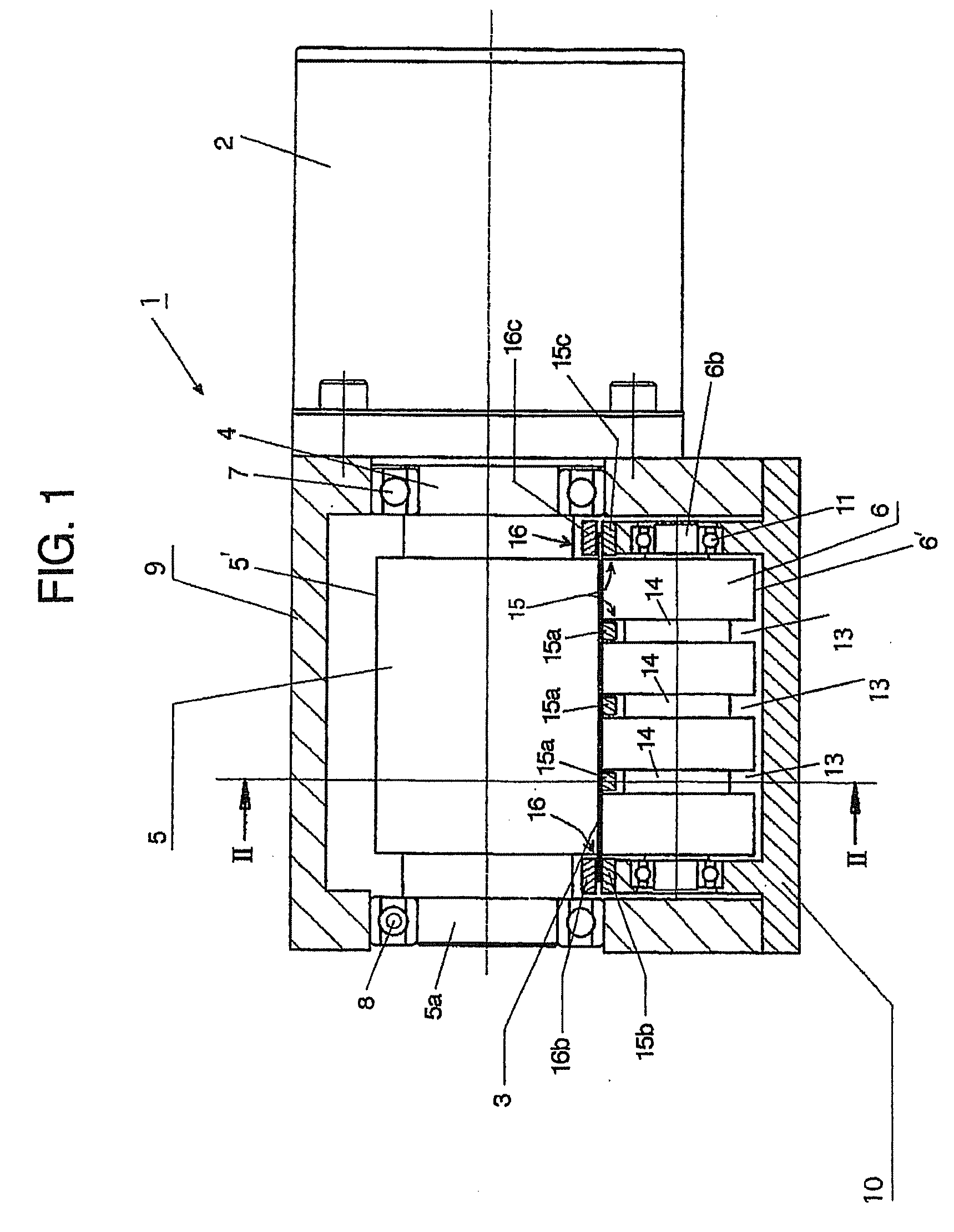
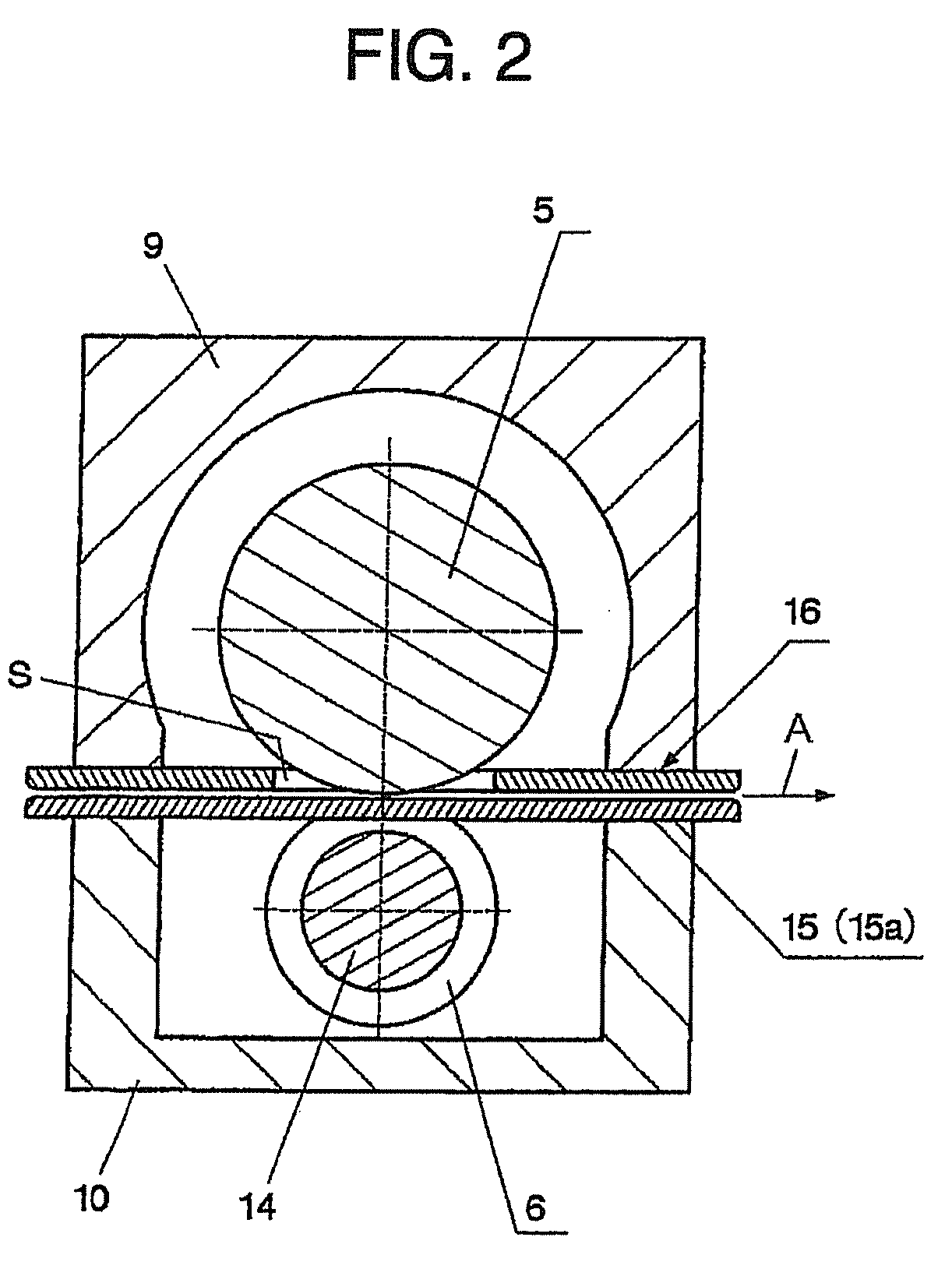
[0022]A sheet material feeding apparatus 1, according to Embodiment 1, shown in FIGS. 1 and 2 comprises a pair of rolls, that is, an upper, main roll 5 driven by a drive device 2 such as servomotor or the like, a lower, sub-roll 6 driven through a sheet material 3 by the main roll 5, and sheet material guide means described later in detail.

[0023]A housing that accommodates therein the main roll 5 and the sub-roll 6 includes a first housing portion 9 having a wall portion that supports the main roll 5, and a second housing portion 10 mounted to the first housing portion 9 to support the sub-roll 6. One end 5b of the main roll 5 is connected to a driving shaft 4 of the drive device 2, the driving shaft 4 being supported rotatably on the first housing portion 9 with a bearing member 7 therebetween. The other end 5a of the main roll 5 is supported rotatably on the first housing portion 9 with a bearing member 8 therebetween. Both ends 6a, 6b of the sub-roll 6, respectively, are supporte...

embodiment 2

[0034]Embodiment 2 shown in FIG. 4 comprises a sub-roll 6 and a first guide member 15, which are the same as those in Embodiment 1, the first guide member 15 having guide portions 15a to 15c being the same as those in Embodiment 1.

[0035]In Embodiment 2, a main roll 5A and a second guide member 16A are structured in the same manner as the sub-roll 6 and the first guide member 15 are.

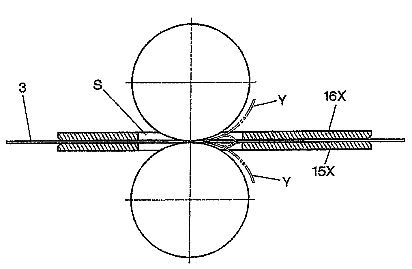
[0036]That is, a sheet material feeding surface 5A′ of the main roll 5A is provided with a plurality of circumferential grooves 13A, which are spaced from one another in an axial direction of a sheet material feeding surface, and small-diameter portions 14A of the main roll 5A are provided in locations, in which the circumferential grooves are provided. The second guide member 16A includes guide portions 16a passing through the respective, circumferential grooves 13A and extending continuously to a downstream side from an upstream side in a sheet-material conveyance direction, and guide portions 16b, 16c ...

embodiment 3

[0039]In Embodiment 3 shown in FIG. 6, a sub-roll 6A includes a roll shaft 30, both ends of which are fixed to a housing of a sheet material feeding apparatus, and a plurality of bearing members 31 mounted in positions spaced from one another in an axial direction of the roll shaft 30. Spacers 32 are provided between the respective bearing members 31. Preferably, deep groove bearings are used for the bearing members 31.

[0040]Outer peripheral surfaces of outer rings 31a of the respective bearing members 31 define sheet material feeding surfaces. Also, a plurality of circumferential grooves 13 are formed in positions between the respective bearing members 31 and guide portions 15a are provided to pass through the respective circumferential grooves 13 and extend continuously to a downstream side from an upstream side in a sheet-material conveyance direction. Guide portions 15b, 15c shown in FIG. 6 are the same as the guide portions 15b, 15c in Embodiments 1 and 2.

[0041]According to Emb...


PUM


Abstract

A sheet material feeding apparatus capable of favorably guiding a sheet material to perform smooth feeding comprises a pair of rolls and first and second guide members and permits a sheet material to pass between the first guide member and the second guide member. One of the rolls has a plurality of circumferential grooves arranged between both ends of a sheet material feeding surface in an axial direction and spaced from one another in the axial direction, and the first guide member includes guide portions passing through the respective circumferential grooves and extending continuously to a downstream side from an upstream side between the pair of rolls in a sheet-material conveyance direction.

Description

BACKGROUND OF THE INVENTION[0001]The present invention relates to a sheet material feeding apparatus that intermittently feeds a sheet material a predetermined quantity by a predetermined quantity to a work machine such as a press apparatus, etc., and more particularly, to a sheet material feeding apparatus suited to feeding of a thin sheet material.[0002]A new technology, such as development of hybrid cars in auto industry, etc., associated with the global environmental problem and products employing the technology are actively developed in respective industries. The hybrid technology of automobiles is based on the combination of an engine and a motor and one of themes of the technology resides in developing a further efficient motor. While motor cores used in such motors are manufactured by laminating thin sheets, which are punched by a press apparatus, in several layers, it has been found that with a view to an improvement in efficiency, it is preferable to make thin sheets, whic...

Claims


Application Information

Patent Timeline
IPC IPC(8): B65H5/06
CPCB65H2404/133B65H2404/14B65H2404/611B65H20/04B65H5/062B65H5/38B65H2701/173B30B15/30B23Q7/05
Inventor KATO, HEIZABURO
Owner SANKYO SEISAKUSHO
Why Eureka
Try Eureka