Brushless motor and cooling fan

Active Publication Date: 2009-04-30
NIDEC CORP
View PDF2 Cites 6 Cited by
  • Summary
  • Abstract
  • Description
  • Claims
  • Application Information

AI Technical Summary

Benefits of technology

[0019]According to the brushless motor and the cooling fan of various preferred embodiments of the present invention, a positional relationship between the position sensor (the Hall device or the Hall IC) and the stator core, and

Problems solved by technology

In particular, a slim fan having a thickness in the axial direction of 15 millimeters or smaller has little margin in the axial dimension, so it is difficult to secure a space between an end surface of the stator core and the Hall device or the Hall IC.
However, if a distanc

Method used


Image

  • Brushless motor and cooling fan
  • Brushless motor and cooling fan
  • Brushless motor and cooling fan

Examples


Example

[0029]Hereinafter, preferred embodiments of the present invention will be described with reference to the attached drawings.

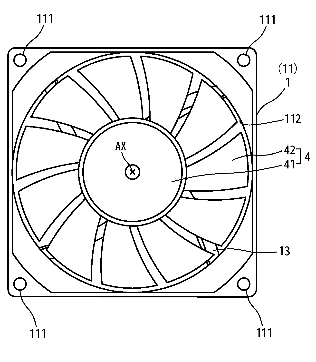
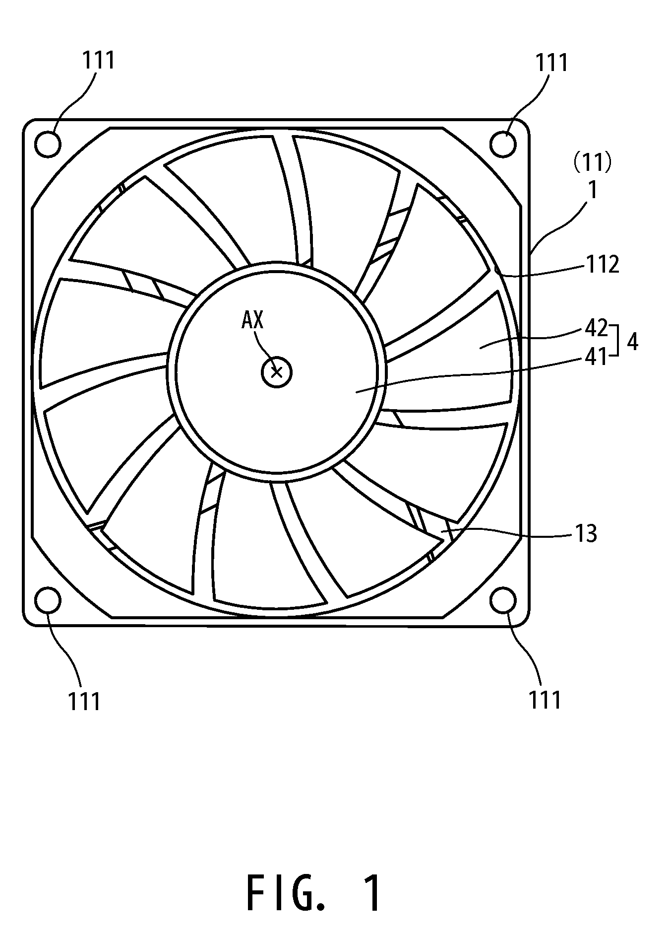
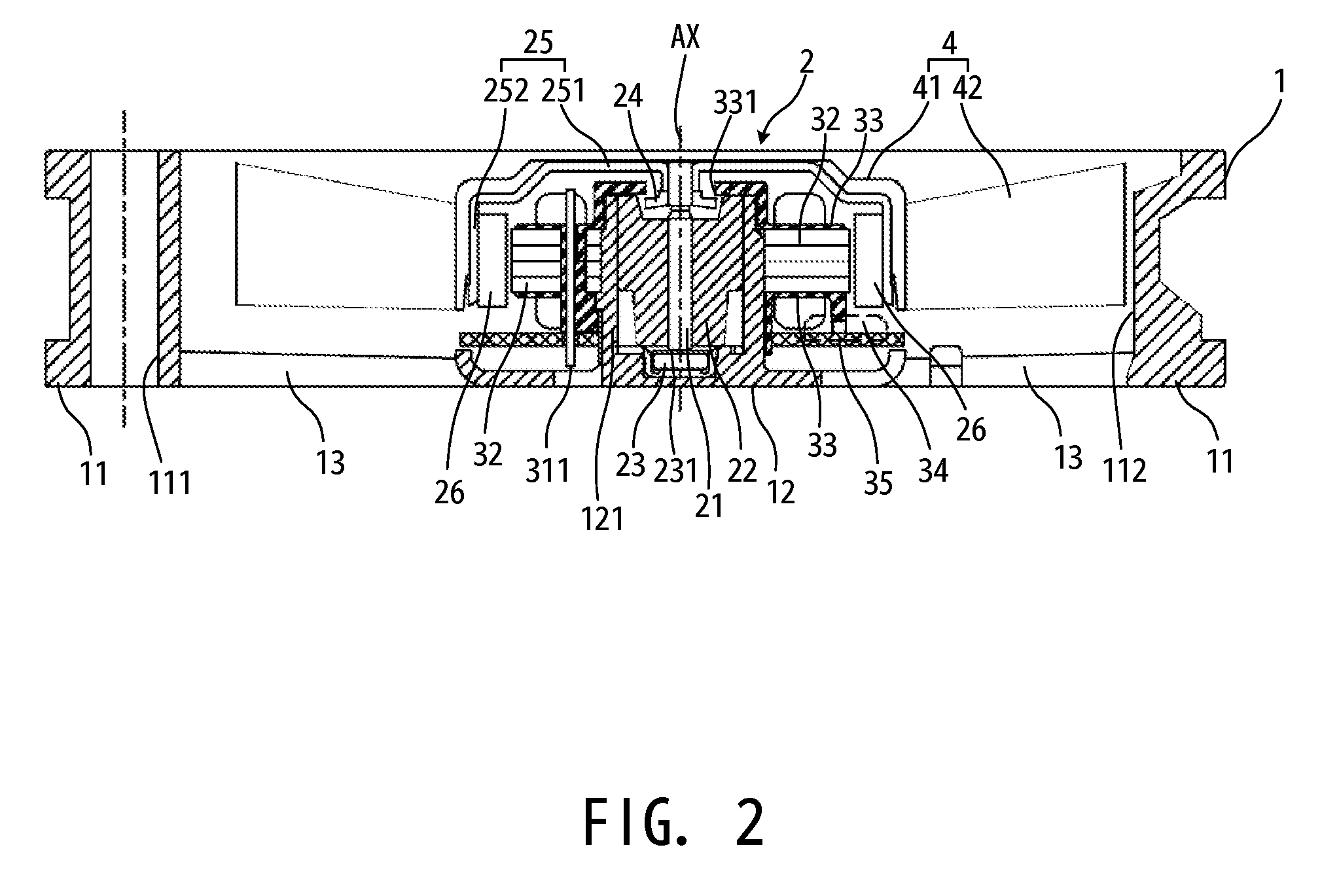
[0030]FIG. 1 is a schematic plan view of a cooling fan using a brushless motor according to a preferred embodiment of the present invention, and FIG. 2 is a schematic cross section of the cooling fan. This cooling fan is an axial fan including a brushless motor 2 and an impeller 4 housed in a housing 1 that is a resin molded part. It is a slim fan having a dimension of about 15 millimeters or less in the direction along the central axis AX, which is a thickness of the housing 1. It also has an outer shape that is preferably substantially square as viewed from the top, each side of which is approximately 60 millimeters.

[0031]The housing 1 includes a cylindrical portion 11 having a substantially circular inner surface and a substantially square outer shape as viewed from the top, a base portion 12 having a substantially circular shape viewed from the top located ...


PUM


Abstract

A rotor unit of a brushless motor includes a substantially cylindrical rotor magnet and a rotor holder arranged to retain an outer circumferential portion of the rotor magnet. A stator unit of the same includes a stator core around which coils are wound and a Hall IC for sensing magnetic flux generated from the rotor magnet. The stator core includes teeth disposed at positions separated in the circumferential direction, each of which has an arm portion extending outward in the radial direction around which the coil is wound, and a stretching portion extending from the arm portion outward in the radial direction and in the circumferential direction on both sides. A sensor element included in the Hall IC is positioned in the range within a lead angle of about four degrees or less as a mechanical angle in the circumferential direction from a line connecting radially the central axis and a point bisecting a line connecting neighboring stretching portions, and within a distance of about one millimeter or smaller outward in the radial direction from an arc connecting outer edges of the neighboring stretching portions.

Description

BACKGROUND OF THE INVENTION[0001]1. Field of the Invention[0002]The present invention relates to a brushless motor and a cooling fan. More specifically, the present invention relates to a layout of a position sensor such as a Hall device or a Hall IC that is used for sensing a magnetic pole position of a rotor in the brushless motor.[0003]2. Description of Related Art[0004]In accordance with a small size and a slim shape of recent electronic equipment, a cooling fan to be used for the equipment is also required to have a small size and a slim shape. In particular, a slim fan having a thickness in the axial direction of 15 millimeters or smaller has little margin in the axial dimension, so it is difficult to secure a space between an end surface of the stator core and the Hall device or the Hall IC. Since the Hall device or the Hall IC senses a magnetic field (or a magnetic flux) generated by a rotor magnet, it is preferable that a distance between the rotor magnet and the Hall devic...

Claims


Application Information

Patent Timeline
IPC IPC(8): H02K11/00F04B17/03
CPCH02K29/08F04D25/0646F04D25/064
Inventor TESHIMA, HIROYOSHIMURAOKA, KOJISAIGA, AKIRA
Owner NIDEC CORP
Why Eureka
Try Eureka