Rectifier, alternator using same and power supply using same

a technology of rectifier and alternator, which is applied in the direction of electronic switching, mechanical energy handling, pulse technique, etc., can solve the problems of large loss of diodes and high cost of rectifying parts of alternators

Active Publication Date: 2018-09-18
HITACHI POWER SEMICON DEVICE
View PDF16 Cites 6 Cited by
  • Summary
  • Abstract
  • Description
  • Claims
  • Application Information

AI Technical Summary

Benefits of technology

[0012]An aspect of the present invention provides a rectifier using an autonomous synchronous rectification MOSFET, an alternator and a power supply using the rectifier, which can perform rectification operations normally without characteristic change due to the high voltage application any time during the rectification operation, during the application of the reverse surge, or during the stop of the vehicle.
[0023]According to the aspect of the present invention, there is provided a rectifier using an autonomous synchronous rectification MOSFET, an alternator and power supply using the rectifier, which can perform rectification operations normally without characteristic change due to the high voltage application any time during the rectification operation, during the application of the reverse surge, or during the stop of the vehicle.

Problems solved by technology

The diode has a large loss due to a large forward voltage drop in spite of a low cost.
The external control type of the synchronous MOSFET needs to use a sensor such as the Hall element and it is necessary to perform a complicated control with a control circuit, so that a rectifying part of the alternator becomes expensive.

Method used


Image

  • Rectifier, alternator using same and power supply using same
  • Rectifier, alternator using same and power supply using same
  • Rectifier, alternator using same and power supply using same

Examples


first embodiment

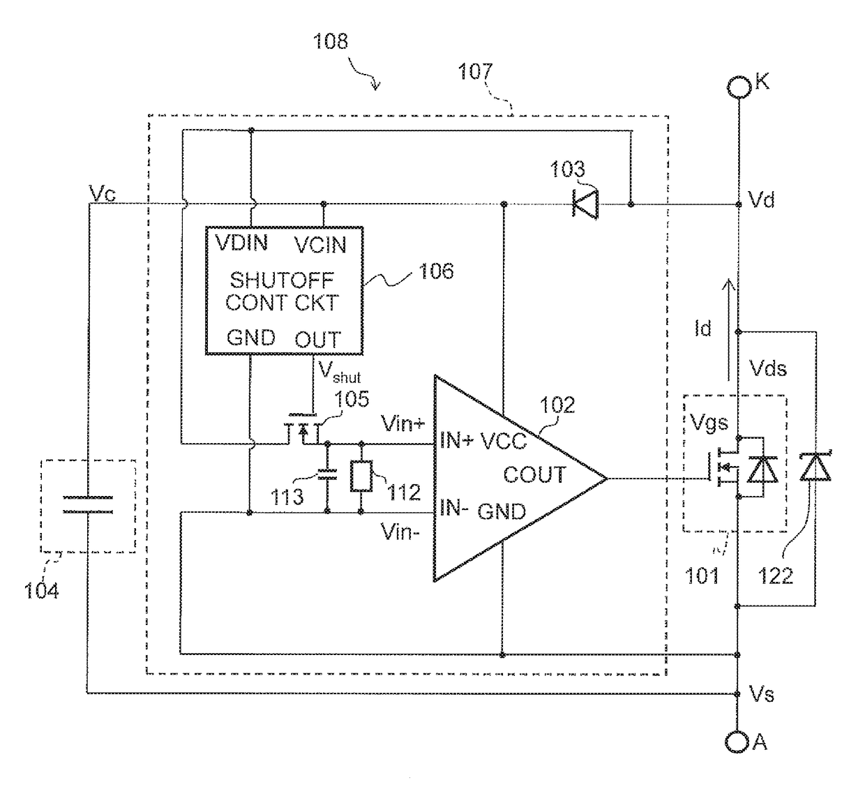
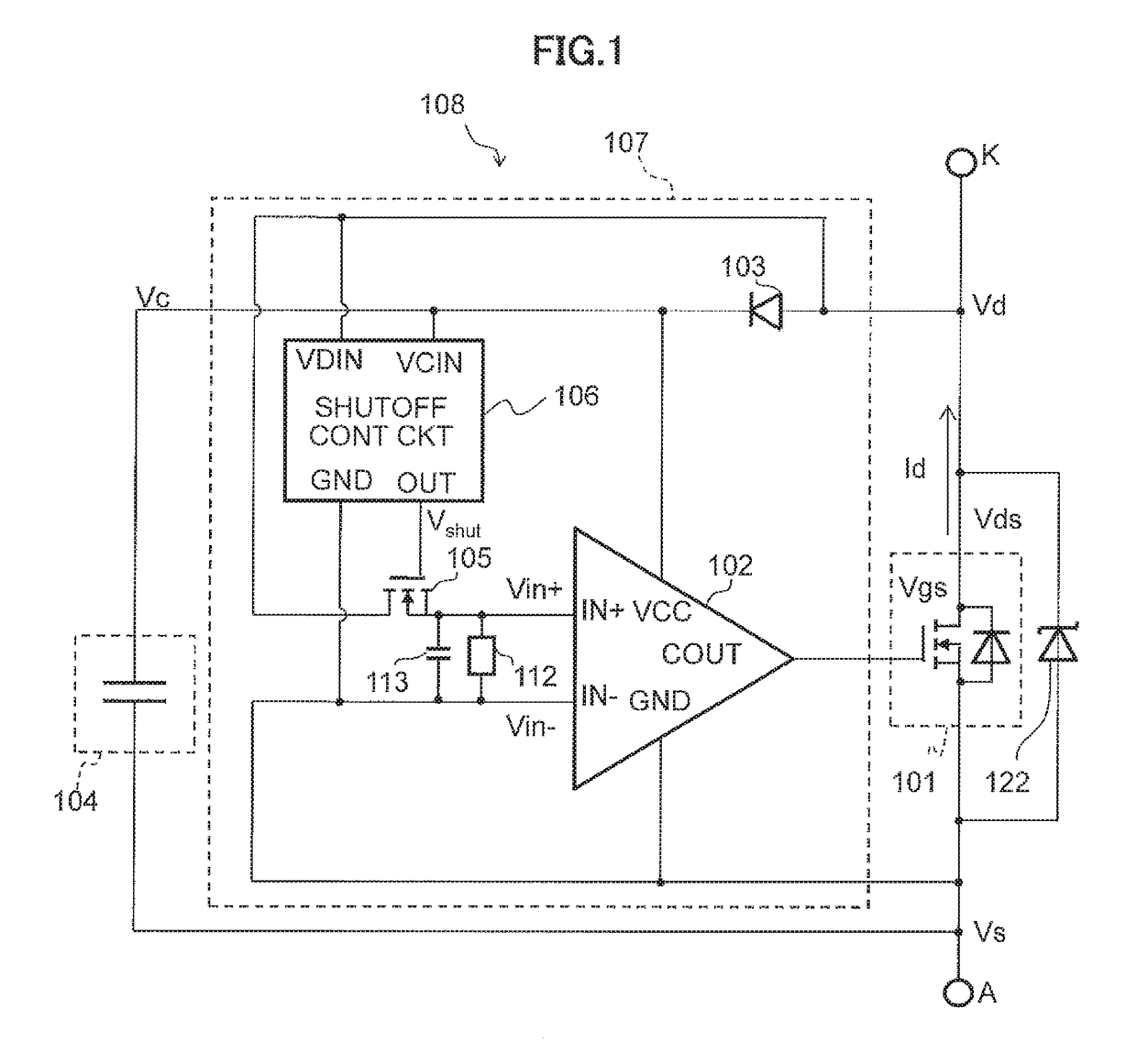
[0052]FIG. 1 is a circuit diagram of a rectifier 108 using an autonomous synchronous rectification MOSFET according to a

[0053]As shown in FIG. 1, the rectifier 108 using the autonomous synchronous rectification MOSFET according to the first embodiment is configured including two external terminals, i.e., a positive-side main terminal K and a negative-side main terminal A, a rectification MOSFET 101, a capacitor 104, and a control circuit 107. Further, the control circuit 107 is configured further including a comparator 102, a diode 103, a shutoff MOSFET 105, a shutoff control circuit 106, a resistive element 112, a capacitor 113, and a Zener diode 122.

[0054]The rectification MOSFET 101 includes a parasitic diode therein and performs rectification. The control circuit 107 includes a comparator 102. A non-inverted input terminal IN+(first input terminal) of the comparator 102 is connected to a drain of the rectification MOSFET 101 through the shutoff MOSFET 105, and an inverted input ...

second embodiment

[0132]FIG. 8 is a circuit diagram of a rectifier using an autonomous synchronous rectification MOSFET according to a

[0133]The rectifier 108A including the autonomous synchronous rectification MOSFET according to the second embodiment includes a shutoff control circuit 106A to which a capacitor voltage output terminal VCOUT is added to the shutoff control circuit 106 relative to the rectifier 108 in the first embodiment shown in FIG. 1, wherein the source voltage terminal VCC of the comparator 102 is connected to the capacitor voltage output terminal VCOUT of the shutoff control circuit 106A. The capacitor voltage output terminal VCOUT outputs a voltage Vcc.

[0134]The gate drive circuit 115 is further provided at the rear stage of the comparator 102. The output terminal COUT of the comparator 102 is connected to the input terminal IN of the gate drive circuit 115, and an output terminal GOUT of the gate drive circuit 115 is connected to the gate of the rectification MOSFET 101. Furthe...

third embodiment

[0181]FIG. 13 is a circuit diagram of an example of a shutoff control circuit 106B included in the rectifier 108B according to the

[0182]In the shutoff control circuit 106B shown in FIG. 13, a PMOS 19 and an NMOS 28 are added to the shutoff control circuit 106A shown in FIG. 12. The PMOS 19 and the NMOS 28 form a CMOS inverter, and an input side of the CMOS inverter is connected to a drain of the PMOS 16. An output side of the CMOS inverter is connected to an output terminal OUT2.

[0183]FIGS. 14A to 14D are charts illustrating an operation of the shutoff control circuit 106B according to the third embodiment. FIG. 14A is a chart illustrating a relation between the voltage Vds and the voltage Vshut. FIG. 14B is a chart illustrating a relation between the voltage Vds and the voltage Vcc. FIG. 14C is a chart illustrating a relation between the voltage Vds and a conduction state of the PMOS 16. FIG. 14D is a chart illustrating a relation between the voltage Vds and the voltage Vshort. Her...


PUM


Abstract

The rectifier includes a rectification MOSFET; a comparator having the non-inverted input terminal connected to a drain of the rectification MOSFET and the inverted input terminal connected to a source of the rectification MOSFET, and the control circuit controlling ON and OFF of the rectification MOSFET by an output of the comparator. The control circuit includes the shutoff MOSFET for performing shutoff between the drain of the rectification MOSFET and the non-inverted input terminal of the comparator and the shutoff control circuit performing electrical shutoff between the drain of the rectification MOSFET and the non-inverted input terminal of the comparator by turning off the shutoff MOSFET when a voltage of the drain of the rectification MOSFET is equal to or higher than a first predetermined voltage.

Description

CROSS REFERENCE TO RELATED APPLICATION[0001]The present application is based on Japanese application JP 2015-206067 filed on Oct. 20, 2015, the content of which is hereby incorporated by reference into this application.BACKGROUND OF THE INVENTION[0002]1. Field of the Invention[0003]The present invention relates to a rectifier using an autonomous synchronous rectification MOSFET (Metal Oxide Semiconductor Field Effect Transistor) and an alternator and a power source using the rectifier.[0004]2. Description of the Related Art[0005]For an alternator for generating electricity in a vehicle, diodes have been used as a rectifying element. The diode has a large loss due to a large forward voltage drop in spite of a low cost. On the other hand, a MOSFET begins to be used as a rectifying element for the alternator in place of the diodes. Use of the MOSFET for synchronous rectification provides a rectifying element having a small loss without a large forward voltage drop in which the forward ...

Claims


Application Information

Patent Timeline
Patent Type & Authority Patents(United States)
IPC IPC(8): H02M1/36H02K7/00H02K11/04H02M7/217H02M1/08H03K17/30H02M7/219
CPCH03K17/302H02K7/006H02K11/046H02M1/36H02M7/217H02M1/08H03K17/30H03K2217/0081H02M7/219H03K2017/307H02K11/05Y02B70/10
Inventor ISHIMARU, TETSUYAKURITA, SHINICHITERAKAWA, TAKESHI
Owner HITACHI POWER SEMICON DEVICE
Why Eureka
Try Eureka