Techniques For Controlling Observed Glare Using Polarized Optical Transmission And Reception Devices

a technology of optical transmission and reception device and observed glare, applied in the field of optics, can solve the problems of affecting the progress of jewelers working on intricate details, affecting the visibility of vehicles, and obscuring important visual information, so as to reduce the visibility of vehicles and enhance visible contras

Inactive Publication Date: 2009-04-30
HAY RANALD JOSEPH
View PDF2 Cites 11 Cited by
  • Summary
  • Abstract
  • Description
  • Claims
  • Application Information

AI Technical Summary

Benefits of technology

[0021]It is an object of the present invention to provide a glare controlling apparatus which selectively controls glare from interposed specular media, so as to enhance visible contrast between (a) objects onto which light is being shed, such as a vehicle in the distance, and (b) rain, snow, and / or fog while, at the same time, not substantially reducing the visibility of the vehicle in the distance.
[0022]Another object of the present invention is to provide a glare controlling apparatus for adjusting the visible contrast of glare and re-emitted light from objects in an outdoor scene onto which light is shed while, at the same time, not eliminating such glare, altogether, thereby providing an additional measure of safety in various system applications.
[0023]A further object of the present invention is to provide a glare adjustment mechanism for enhancing a photographed or viewed scene while, at the same time, not eliminating glare-producing objects from the scene.

Problems solved by technology

This visual noise can adopt any of various forms, from the inconvenient to the dangerous.
When light reflections from these noise sources are aggregated, the amount of overall visual noise may obscure important visual information in the distance.
In addition to driving, light glare is a problem in many other settings.
Specular glare from reflective surfaces can impede the progress of jewelers working on intricate details.
Specular glare also causes problems with certain types of surveillance equipment.
However, specular glare from reflective bright surfaces, such as glass, may overload the sensitive light amplifier tube, causing momentary “glare blindness” that lasts for as long as several seconds.
Invisible infrared illuminators are often utilized in critical operational environments, such as law enforcement and national defense, where a blinding delay of a few seconds could have devastating and far-reaching consequences.
However, no mechanism is provided to readily adjust the direction of polarization of the transmitted light.
In addition, no mechanism is provided to adjust the polarization of light to be filtered out at the observers's eyes.
Finally, this system is limited in application to automotive headlamps and the like, and is not adaptable to solving a broader range of light glare problems.
Unfortunately, as in the case of the Humphrey patent, no mechanism is provided for distinguishing desired visual information from noise.
Moreover, by its very nature, the Farwig technique is only applicable to visible light, and cannot be adapted to infrared wavelengths.
Although this geometry might maximize the reduction of visible glare, it does not represent the desired arrangement for many photographic or other types of scenes.
Depending upon the orientation of the flash unit and the lens relative to a scene, as well as the orientation of reflective objects within the scene, the fixed positions of the first and second filters may not be optimally situated to achieve a desired amount of glare reduction.
Moreover, this approach only considers transient glare that is generated by the flash unit, whereas a photographic scene may be continually illuminated by other glare-producing light sources.
Moreover, Jasgur provides no teaching related to enhancing visibility in the presence of a substantial multiplicity of specular particles which, when analyzed as an aggregate entity, constitute, an atmospheric phenomenon.
However, adoption of this approach in other fields, such as aviation, boating, or motor vehicle technology, raises serious safety concerns.
Using the approach outlined in Meyer and Jasgur, full or maximum elimination of any tell tale reflections from this vehicle may well result in a collision, especially if the headlamps on the grey vehicle are not illuminated.
Unfortunately, the prior art approach of Meyer and Jasgur does not allow for this safety trade-off.
However, glare elimination is not the same thing as glare control.
Neither the Brooks nor the Land patents disclose a mechanism for reducing glare from reflective atmospheric media or brilliant reflective objects in the distance.

Method used


Image

  • Techniques For Controlling Observed Glare Using Polarized Optical Transmission And Reception Devices
  • Techniques For Controlling Observed Glare Using Polarized Optical Transmission And Reception Devices
  • Techniques For Controlling Observed Glare Using Polarized Optical Transmission And Reception Devices

Examples


Embodiment Construction

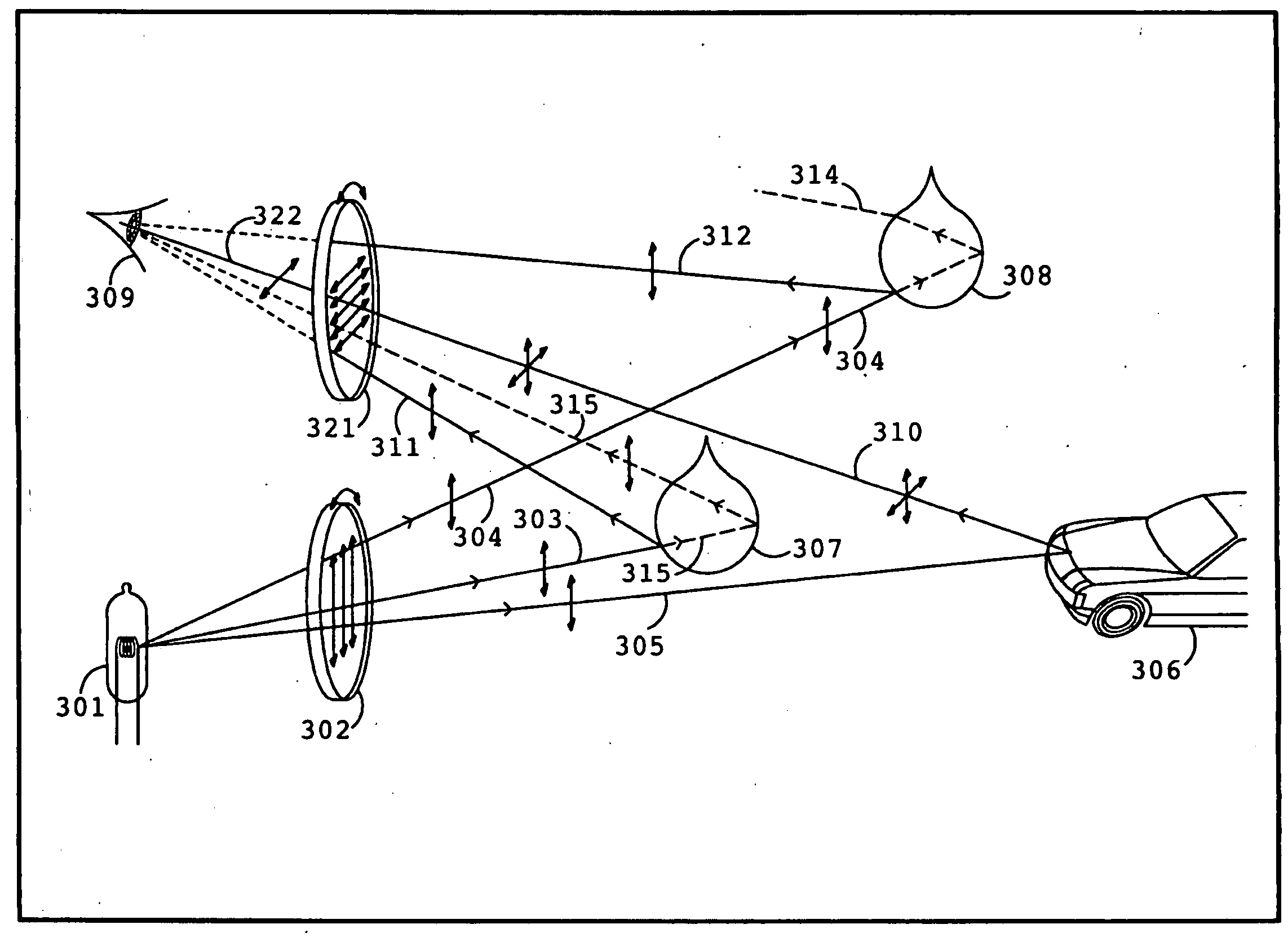
[0039]In overview, the invention is directed to a visibility enhancing system that includes an adjustment mechanism for adjusting the polarization of a light source relative to the polarization of a viewing filter, so as to improve visual contrast between interposing specular media and an object to be viewed. The light source includes a light generation mechanism for generating polarized light, and an optional source polarization angle determination mechanism for adjusting the angle of polarization of the light source. The viewing filter includes a filter polarization. angle adjustment mechanism for adjusting at least one of the polarization angle of maximum light attenuation and the polarization angle of minimum light attenuation. An observer adjusts at least one of the source polarization angle determination mechanism and the filter polarization angle adjustment mechanism so as to improve the visibility of the object to be viewed in the presence of interposed specular media.

[0040]...


PUM


Abstract

Systems and methods that utilize an adjustment mechanism for adjusting the polarization angle of a light source relative to the polarization angle of a viewing filter, so as to permit adjustment of visual contrast between interposed specular media and an object to be viewed and / or photographed, wherein the interposed specular media is an atmospheric phenomenon comprising a seemingly infinite number of dispersed specularly reflective particles enveloping at least one of an observer or a scene of interest. The light source includes a light generation mechanism for generating polarized light, and an optional source polarization angle determination mechanism for adjusting the angle of polarization of the light source. The viewing filter includes a filter polarization angle adjustment mechanism for adjusting at least one of the polarization angle of maximum light attenuation and the polarization angle of minimum light attenuation.

Description

RELATED APPLICATIONS[0001]This is a Divisional application of pending application Ser. No. 11 / 509,911 filed on Aug. 25, 2006, which is a Continuation-In-Part of abandoned patent application Ser. No. 10 / 629,874 filed on Jul. 28, 2003, which is a Continuation-In-Part of abandoned patent application Ser. No. 09 / 756,898, filed on Jan. 9, 2001, and based on which priority is herewith claimed under 35 U.S.C. 120 and the entire disclosures of which are fully incorporated herein.FIELD OF THE INVENTION[0002]The present invention relates generally to the field of optics, and, more specifically, to devices and techniques for controlling reflected glare.BACKGROUND ART[0003]“Glare” may be conceptualized as a form of visual noise included within a scene containing visual information. This visual noise can adopt any of various forms, from the inconvenient to the dangerous. For example, when driving towards the sun, an icy road is transformed into a sea of fire. Such a situation may exist whenever ...

Claims


Application Information

Patent Timeline
Patent Type & Authority Applications(United States)
IPC IPC(8): G02B27/28F21S8/10F21V9/14G02B7/00G02B26/00G02B27/00
CPCF21S48/114F21V9/14G02B27/281G02B26/00G02B7/003F21S41/135
Inventor HAY, RANALD JOSEPH
Owner HAY RANALD JOSEPH
Why Eureka
Try Eureka