Computed tomography with resolution recovery

Active Publication Date: 2009-04-30
XORAN TECH
View PDF17 Cites 26 Cited by
  • Summary
  • Abstract
  • Description
  • Claims
  • Application Information

AI Technical Summary

Benefits of technology

[0009]In another aspect of the invention, the controller pre-computes a model of the shift variant blur based on the location, orientation, and size of the target. For example, the angle between the target and the sensing array may be used

Problems solved by technology

The projection of an extended focal spot onto

Method used


Image

  • Computed tomography with resolution recovery
  • Computed tomography with resolution recovery
  • Computed tomography with resolution recovery

Examples


Embodiment Construction

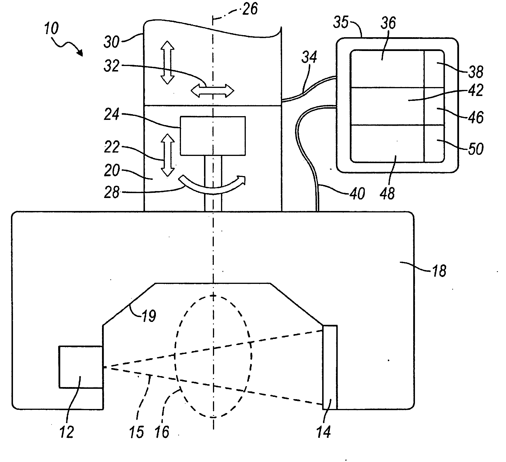
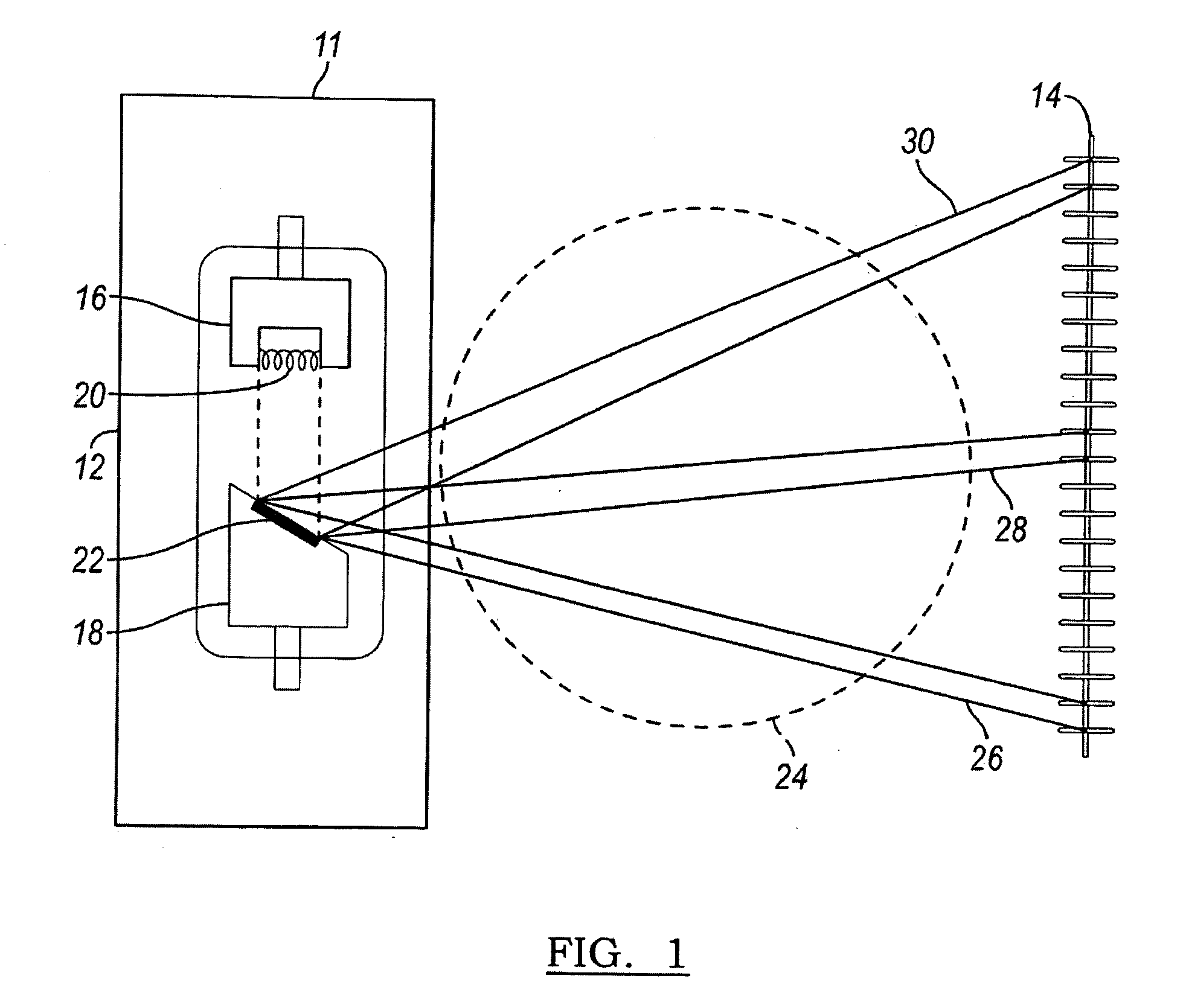
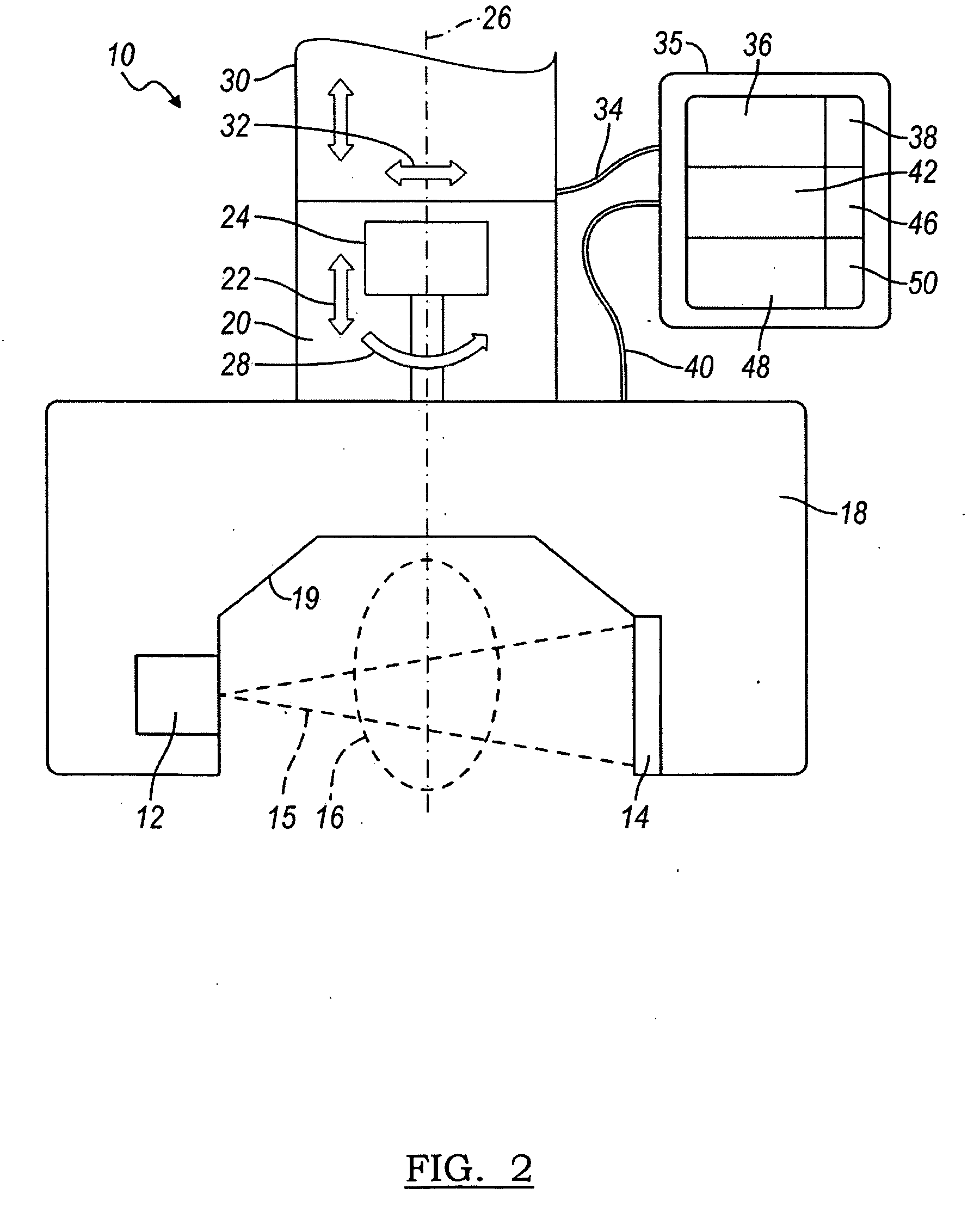
[0019]An x-ray computed tomography system illustrating shift variant blur is provided in FIG. 1. The system 10 contains an x-ray source 11 and a detector 14. The x-ray source 11 includes an x-ray tube 12 with a cathode 16 and an anode 18. The cathode 16 has a filament 20, such as a linear filament. X-rays are generated as electrons jump across the x-ray tube 12 from the filament 20 to a target 22 on the anode 18 of the x-ray tube 12. The filament 20 forms an extended line source on the target 22. However, the target 22 is angled so that there is a relatively oblique projection of the line source onto the detector 14. The detector 14 may be a pixilated detector, such as linear array detector or a two-dimensional detector array, for example an amorphous silicon flat panel (coupled with a scintillation crystal), a traditional multi row computed tomography detector, or other similar imaging detectors.

[0020]The x-rays are projected from the x-ray source11 through the object 24 and onto t...


PUM


Abstract

A system and method for recovering resolution in an x-ray computed tomography system. The system includes an x-ray source, a two-dimensional sensing array, and a controller. The x-ray source projects an x-ray beam towards subject. The x-ray source includes an anode and a cathode, where the anode has a target for directing the x-ray beam. A two-dimensional sensing array receives an x-ray beam through the subject to generate an image. The target of the anode causes a shift variant blur of the x-ray beam received by the sensing array due to the angle between the target and the sensing array. The controller is in communication with the sensing array to control acquisition and processing of the image. The controller is configured to adjust for the shift variant blur of the x-ray beam.

Description

CROSS-REFERENCE TO RELATED APPLICATIONS[0001]The present invention claims priority to U.S. Provisional Ser. No. 60 / 984,093, filed Oct. 31, 2007, entitled “Computed Tomography with Resolution Recovery”, which is herein incorporated by reference.BACKGROUND[0002]1. Field of the Invention[0003]The present invention generally relates to a system and method for recovering resolution in an x-ray computed tomography system.[0004]2. Description of Related Art[0005]In a typical x-ray computed tomography system, an x-ray source projects an x-ray beam through an object and onto a detector. The x-ray source is generally thought of as a point source. However, the focal spot of the x-ray source is actually projected onto a surface and, therefore, has a different apparent size and shape depending on the perspective angle relative to the surface. The projection of an extended focal spot onto the detector may result in significant blur. This system blur is shift variant and depends on the exact geome...

Claims


Application Information

Patent Timeline
IPC IPC(8): A61B6/00
CPCA61B6/032A61B6/4028Y10S378/901A61B6/583H04N5/32
Inventor STAYMAN, JOSEPH W.
Owner XORAN TECH
Why Eureka
Try Eureka