
Refrigerant compressor

a refrigerant compressor and hermetically sealed technology, which is applied in the direction of machines/engines, rotary/oscillating piston pump components, liquid fuel engines, etc., can solve the problems of adverse effect on achieve the optimization of the efficiency of the refrigerant compressor, reduce heat transmission, and reduce efficiency loss

Inactive Publication Date: 2009-04-30
ACC AUSTRIA GMBH
View PDF9 Cites 6 Cited by
  • Summary
  • Abstract
  • Description
  • Claims
  • Application Information

AI Technical Summary

Benefits of technology

[0014]It is therefore the object of the present invention to reduce the efficiency losses caused by the heating of the aspirated refrigerant in the area of the connection openings of the compressor housing and to optimize the efficiency of the refrigerant compressors. A connection apparatus is to be provided for this purpose which considerably reduces the heat transmission between the compressor housing and suction pipe or pressure pipe, so that the lowest possible temperature level of the refrigerant is ensured at the beginning of the compression process, i.e. during the aspiration into the cylinder of the piston-cylinder unit.
[0019]Since the heat transmission from the compressor housing to the suction pipe or from the hot pressure pipe to the compressor housing and subsequently from the same to the suction pipe is reduced, a considerable reduction of the temperature of the refrigerant which is guided in the suction pipe and is directly before the compression process in the piston-cylinder unit is achieved, thus leading to an increase in the efficiency of the refrigerant compressor. By avoiding the heat transmission from the hot pressure pipe to the compressor housing, a heating of the compressor housing itself and the interior of the compressor housing (oil, the refrigerant disposed in the interior, compressor housing temperature) is reduced, leading to an improvement in the efficiency.
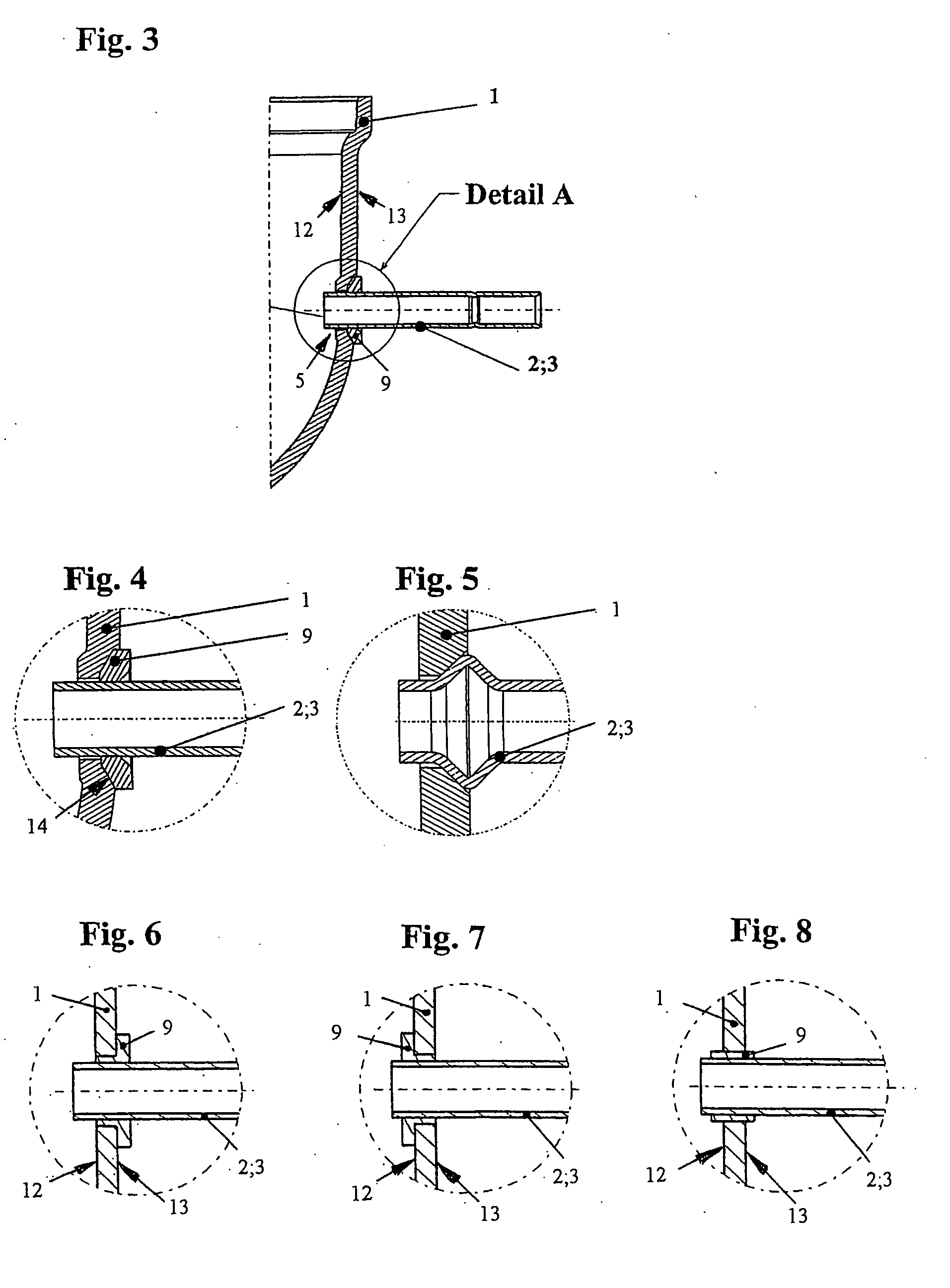
[0022]According to another preferred embodiment of the invention, the spacer element is made of foamed glass, plastic or a ceramic material according to the characterizing features of claim 4. The mentioned materials lead to a strong reduction of the undesirable heat transmission from the compressor housing or the body element in direct contact with the same to the suction pipe and vice-versa from the pressure pipe to the body element and the compressor housing as a result of their low heat transmission coefficient.
[0023]In addition to a direct arrangement of a separate spacer element having an insulating effect between the body element and the suction pipe or pressure pipe according to the characterizing features of claim 5, with the suction pipe or pressure pipe being enclosed by the spacer element in a hermetically sealing manner, it is also possible in an alternative embodiment to arrange the body element and the spacer element as an integral component. As such it is provided for according to the characterizing features of claim 6 that the spacer element is arranged as a section, preferably an end section of the body element, which extends under an angular inclination, preferably a right angle, relative to the axis of the suction pipe or pressure pipe in order to enclose the suction pipe or pressure pipe in a hermetically sealing manner. Since this geometry also leads to the consequence that the inside diameter of the body element (with the mere exception of its end section) is always larger than the outside diameter of the suction pipe / pressure pipe, an air cushion is formed between the suction pipe / pressure pipe which has an insulating function and strongly reduces the undesirable heat transmission between the suction pipe / pressure pipe and the compressor housing. This embodiment allows a simple and economical production of the connection apparatus.
[0026]According to the characterizing features of claim 9, the body element comprises a contact section which is fastened to the one on the outside of the compressor housing. The diameter of the connection opening is preferably larger than the outer diameter of the section of the body element which is led through the connection opening. It is thus ensured that an abutting surface of the connection opening does not touch the body element, but remains spaced from the same. This measure too ensures that the insulating function of the connection apparatus in accordance with the invention is increased and the heat transmission between the suction pipe / pressure pipe and compressor housing is reduced.

Problems solved by technology

Since the drawn refrigerant is thus heated, there is an adverse effect on the efficiency of the refrigerant compressor.

Method used


Image

  • Refrigerant compressor
  • Refrigerant compressor
  • Refrigerant compressor

Examples


Embodiment Construction

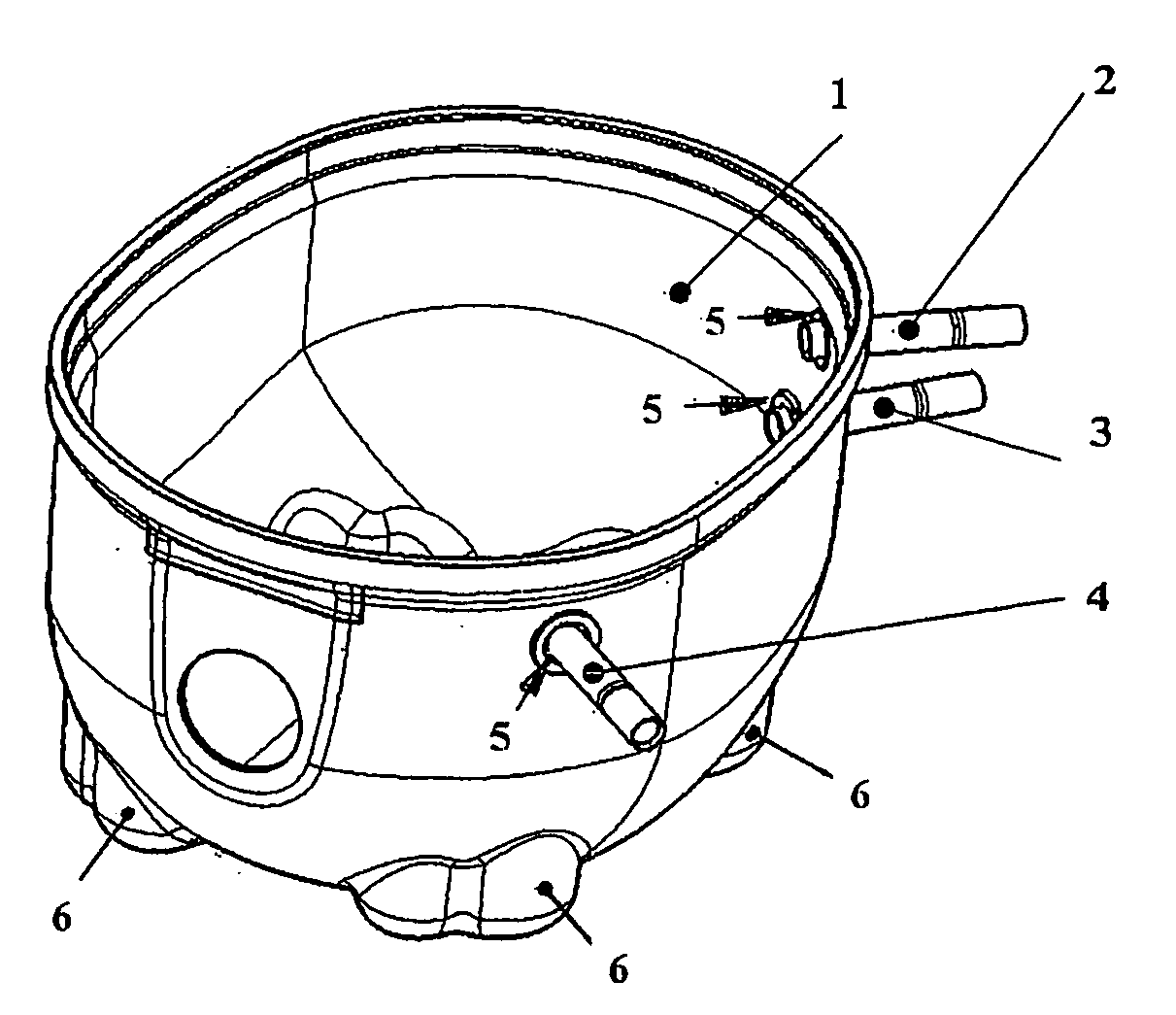
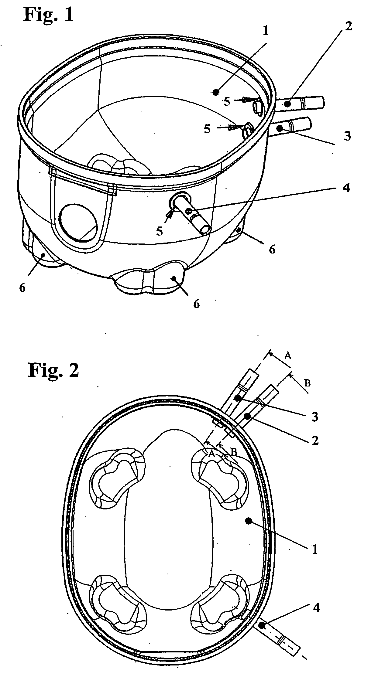
[0041]A refrigerant compressor comprises a hermetically sealed compressor housing 1, with a suction pipe 2, a pressure pipe 3 and a service pipe 4 opening into the same via connection openings 5.

[0042]A refrigerant flows via the suction tube 2 in the known manner to a piston-cylinder unit (not shown) which is arranged within the compressor housing 1 and in which a compression of the refrigerant occurs, with the pressure pipe 3 subsequently leading the compressed and therefore strongly heated refrigerant from the piston-cylinder unit out of the compressor housing 1 to a cooling circuit (also not shown) of a cooling space. The piston-cylinder unit is driven by an electromotor via a crankshaft, so that cooling space associated with the refrigerant compressor is continually cooled by means of the circulating refrigerant.

[0043]Compressor housing 1 comprises several standing elements 6 which are used to position the same on a floor space of a refrigerating device determined for this purpo...


PUM


Abstract

A hermetically encapsulated refrigerant compressor which comprises a hermetically sealed compressor housing (1), in the interior of which a piston-cylinder unit which compresses a refrigerant and a suction pipe (2) and a pressure pipe (3) are provided, with refrigerant flowing via the suction pipe (2) to the piston-cylinder unit and the refrigerant compressed by the piston-cylinder unit being conveyed out of the compressor housing (1) via the pressure pipe (3), with connection openings (5) for the suction pipe (2) and the pressure pipe (3) being provided on the compressor housing (1), with the connection of the suction pipe (2) and pressure pipe (3) to the connection openings (5) occurring in a hermetically tight manner by means of a connection apparatus (9) and with the connection apparatus (9) comprising a preferably sleeve-like body element (8) and at least one spacer element (7) which spaces the body element (8) from the suction pipe (2) / pressure pipe (3). It is provided in accordance with the invention that the body element (8) is attached to an outside (13) of the compressor housing (1) outside of the connection opening (5) by enclosing the same in a hermetically sealing manner.

Description

BACKGROUND OF THE INVENTION[0001]The present invention relates to a hermetically encapsulated refrigerant compressor which comprises a hermetically sealed compressor housing, in the interior of which a piston-cylinder unit which compresses a refrigerant and a suction pipe and a pressure pipe are provided, with refrigerant flowing via the suction pipe to the piston-cylinder unit and the refrigerant compressed by the piston-cylinder unit being conveyed out of the compressor housing via the pressure pipe, with connection openings for the suction pipe and the pressure pipe being provided on the compressor housing which enable the overflow of the refrigerant from the outside of the compressor housing into the interior of the compressor housing and vice-versa, with the connection of the suction pipe and pressure pipe to the connection opening occurring in a hermetically tight manner by means of a connection apparatus, with the connection apparatus comprising a preferably sleeve-like body ...

Claims


Application Information

Patent Timeline
Patent Type & Authority Applications(United States)
IPC IPC(8): F04C29/00
CPCF04C23/008F04C2240/30F04C2230/60F04C29/04F04B39/123F04C2240/806
Inventor BRABEK, WALTERJOST, MANFRED
Owner ACC AUSTRIA GMBH
Learn More