Brachytherapy Apparatus and Method Using Rotating Radiation Source

a radiation source and brachytherapy technology, applied in radiation therapy, therapy, etc., can solve the problem that isotope sources cannot in principle be modulated, and achieve the effect of reducing the dwell time of the source, increasing the distance from the source, and reducing the penetration distance or dose intensity

Inactive Publication Date: 2009-04-30
XOFT INC
View PDF4 Cites 1 Cited by
  • Summary
  • Abstract
  • Description
  • Claims
  • Application Information

AI Technical Summary

Benefits of technology

[0014]Since the shape of the balloon and cavity is substantially predetermined by the resection and balloon choice, the bowed shape of the source guide can be fashioned to follow the cavity wall, preferably but not necessarily at a constant distance, with either style of bowed member. When a source positioned within such a bowed guide is translated axially, coordinated rotation of the guide tube by an external manipulator will sweep the source throughout the cavity at a uniform distance from the cavity wall. Thus the distance to the wall, and the amount of attenuating medium between the source and the cavity wall, will be constant; therefore the radiation incident on the cavity wall will be uniform, as will the dose at the prescription depth, although lower than at the wall. The translation and rotation of the source in the bowed guide tube can approximate a spherical source emitting from everywhere on its surface, so dose does not fall off in an inverse square relationship to distance but falls off a small amount with distance because of the spherical geometry. The source, if isotropic, can be partly shielded such that backward emissions (opposed to the preferred direction) may be substantially eliminated.
[0015]Importantly, when a small cavity is to be used, the radiation emissions can be directed away from the nearest portion of the cavity surface. Since the radiation intensity of an isotropic source decreases exponentially with distance, increasing the distance from the source to the tissue at which the radiation is directed has the effect of reducing the distant cavity-surface incident dose in relation to the prescription dose. In this case, and again only where the source is isotropic, shielding can be applied to the part of the source guide circumference nearest to the cavity surface such that radiation emanating from within the guide would be substantially eliminated on the cavity surfaces nearest the radiation source. Where the source is directed and aimed away from nearby cavity surfaces, however, no shielding is necessary to produce the same effect.
[0016]If imaging has revealed radiation sensitive anatomy unacceptably close to the treatment cavity, the treatment plan can include an over-ride which can interrupt the uniform dose delivery process such that sensitive tissues are spared an overdose and risk of tissue necrosis. Alternatively, radiation sensors placed on or within the body near the at-risk structures can provide monitoring, providing outputs to the system controller signaling the need for a locally reduced dose. Such sensors can be placed using adhesives or needle methods, and power and signal communication can be by conventional wiring or by known wireless methods. Such over-ride might take the form of reduced dwell time of the source when directed toward such structures, or where an x-ray source capable of modulation is used, a reduction in penetration distance or dose intensity can be employed, including shut-off of the source.
[0018]With the methods suggested above, planning is simpler, the ratio of dose incident on the cavity surface to prescription dose at prescription depth can be decreased, and dose accuracy can be improved in many instances. The risk of tissue necrosis is thus minimized, and the proportion of patients for which brachytherapy is indicated is increased.

Problems solved by technology

Isotope sources cannot in principle be modulated, however.

Method used


Image

  • Brachytherapy Apparatus and Method Using Rotating Radiation Source
  • Brachytherapy Apparatus and Method Using Rotating Radiation Source
  • Brachytherapy Apparatus and Method Using Rotating Radiation Source

Examples


Embodiment Construction

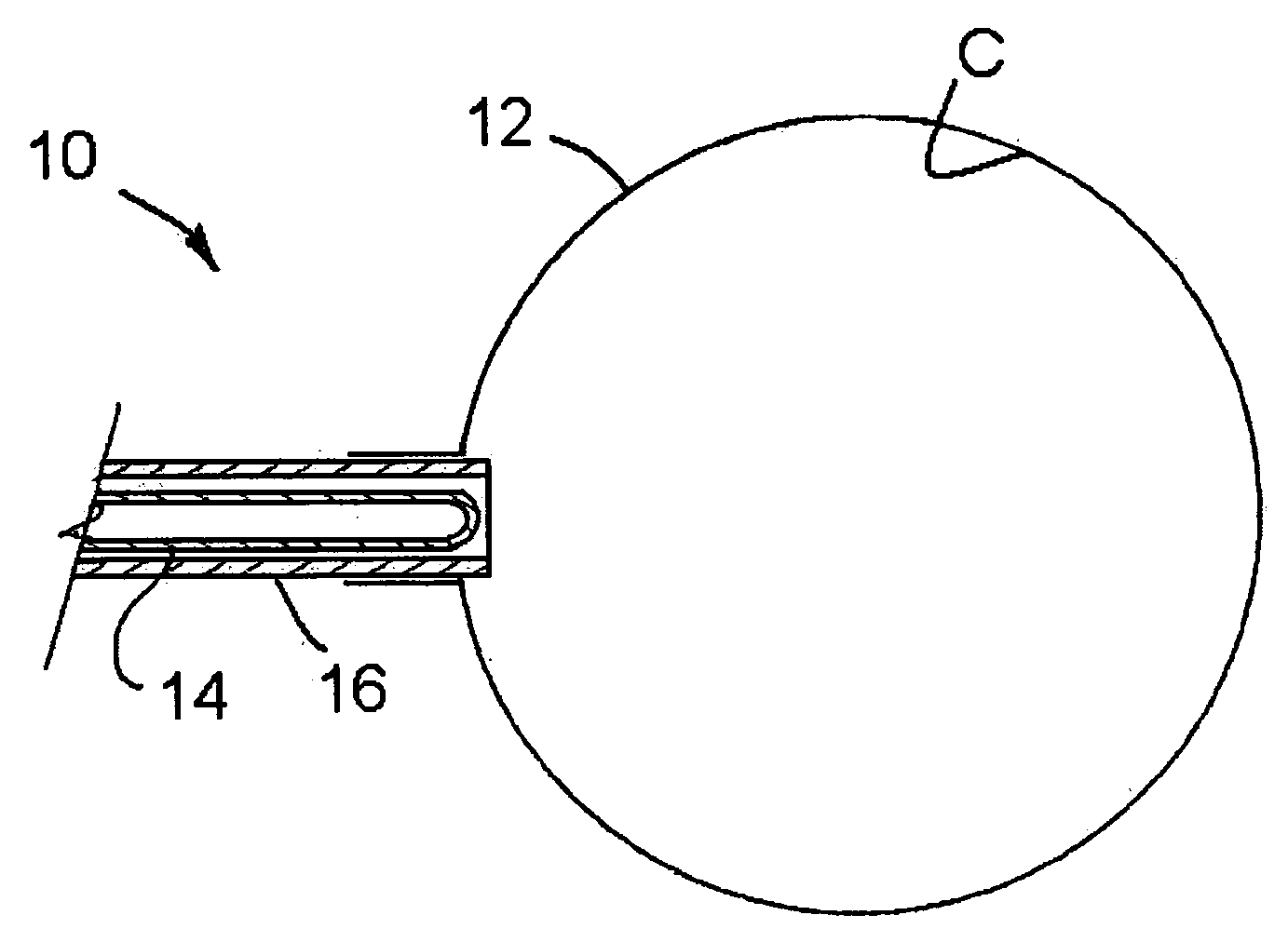
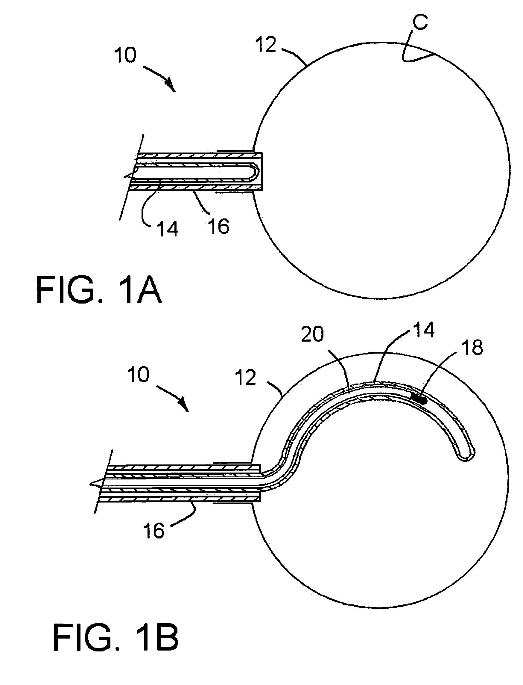
[0029]FIG. 1A depicts the balloon portion of an applicator of the invention. The balloon 12 is shown inflated with fluid, preferably by a liquid, filling and shaping the resection cavity C. The tip of a self-deploying source guide 14 is shown positioned within a shaft 16 fixed to the balloon of the applicator, in preparation for advancement into the balloon 12. One material of which such a source guide might be fashioned is superelastic Nitinol. Such a Nitinol guide can be fabricated in a preferred final bowed shape, but when stress is applied, the guide can be forced into another form and restrained in its new shape. When the restraint is removed, the guide will again resume its original shape as fabricated.

[0030]In FIG. 1A, the applicator shaft 16 provides the restraint to hold the fabricated shape of the guide 14 in a substantially straight configuration, although the fabricated shape of the guide 14 is a bowed shape along the distal portion which will be inserted into the volume...


PUM


Abstract

A brachytherapy applicator and method of use involve a source guide that assumes a desired curving, non-linear configuration when inserted into an inflated balloon of the applicator. A flexible source catheter follows the shape of the source guide when inserted into the balloon. Radiation dose received in various tissue areas can be better controlled using the invention, and the ratio of cavity surface dose to prescription depth dose can be lowered. With rotation of the curving source guide coupled with translation of the source via longitudinal movement of the catheter, the applicator can approximate a spherical source, through either stepped or continuous movement of the source and source guide.

Description

BACKGROUND OF THE INVENTION[0001]This invention concerns radiation therapy, especially brachytherapy, for treating tissues which may have diffuse proliferative disease.[0002]In brachytherapy, a radiation source is generally placed within a surgically created or naturally occurring cavity in the body. In particular, this invention relates to delivery of radiation therapy to tissue as might be found in the human breast, or to other tissue, preferably by activation of a miniature, electronic x-ray source. Such therapy often follows surgical treatment of cancer.[0003]Radiation therapy following tumor resection or partial resection is generally administered over a period of time in partial doses, or fractions, the sum of which comprises a total prescribed dose. This fractional application takes advantage of cell recovery differences between normal and cancerous tissue whereby normal tissue tends to recover between fractions, while cancerous tissue tends not to recover.[0004]With conventi...

Claims


Application Information

Patent Timeline
Patent Type & Authority Applications(United States)
IPC IPC(8): A61N5/00
CPCA61N5/1001A61N5/1015A61N5/1014
Inventor LOVOI, PAUL A.HEANUE, JOSEPH A.
Owner XOFT INC
Why Eureka
Try Eureka