Spacer device and insertion instrument for use in anterior cervical fixation surgery

a spacer device and anterior cervical spine technology, applied in the field of anterior cervical spine surgery medical instruments, can solve the problems of significant pain, particularly complex connective tissue of the neck, and achieve the effects of facilitating fusion, stimulating bone growth, and convenient fitting

Inactive Publication Date: 2009-04-30
HOWMEDICA OSTEONICS CORP
View PDF19 Cites 5 Cited by
  • Summary
  • Abstract
  • Description
  • Claims
  • Application Information

AI Technical Summary

Benefits of technology

[0021]In operation to remove the heads from the spacer while holding the spacer in the intervertebral space, the distal end of the bracing rod is held against the spacer by the surgeon while the surgeon pulls the handles. The pulling of the handles while the spacer is held in the intervertebral space causes the protrusions to slide out of the grooves until the spacer is released from the heads and is compressed between the vertebral discs by the natural compression force present in the spine. Accordingly, the upper and lower surfaces of the spacer, being curvate, easily fit into and remain in the intervertebral space, with each curvate surface seating within the vertebral cavity presented to the surface when the spacer is disposed in the intervertebral space. Further, the surfaces being rough, stimulate bone growth, and being porous, provide for bone growth into the material to facilitate fusion.

Problems solved by technology

The bones and connective tissue of the neck, or cervical spine, are particularly complex in that they are smaller, are the most flexible in the spinal column, and are adjacent to the most critical circulatory, respiratory, and digestive tissues in the body.
These and other failure modes can cause significant pain as well as catastrophic neurological problems.
Concerns for the overall safety of this method of treatment, however, include the risk of screw pull out and / or breakage, or plate breakage, each of which are accompanied by the severe risk of esophegeal perforation, which can be fatal if not treated immediately and aggressively.
The problem is that the distraction increases the distance between the fusing bones, and the need to create the bone bridge requires that the bones be close enough to grow together.

Method used


Image

  • Spacer device and insertion instrument for use in anterior cervical fixation surgery
  • Spacer device and insertion instrument for use in anterior cervical fixation surgery
  • Spacer device and insertion instrument for use in anterior cervical fixation surgery

Examples


Embodiment Construction

[0026]While the present invention will be described more fully hereinafter with reference to the accompanying drawings, in which particular embodiments and methods of implantation are shown, it is to be understood at the outset that persons skilled in the art may modify the invention herein described while achieving the functions and results of this invention. Accordingly, the descriptions that follow are to be understood as illustrative and exemplary of specific structures, aspects and features within the broad scope of the present invention and not as limiting of such broad scope. Like numbers refer to similar features of like elements throughout.

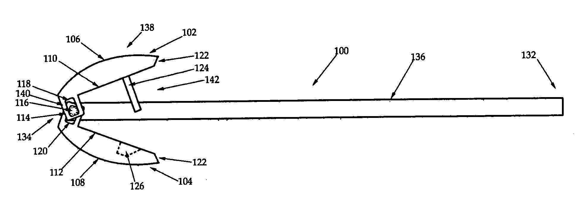
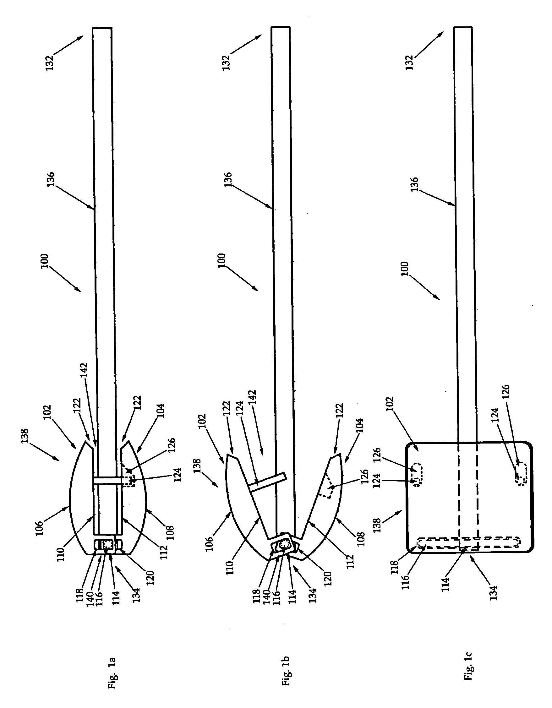
[0027]Referring now to FIGS. 1a-c, an intervertebral distraction tool 100 is shown in two side views (FIG. 1a where the trial 100 is closed, and FIG. 1b where the trial 100 is open) and a top view, respectively. The trial 100 has a proximal end 132 and a distal end 134, the proximal end 132 being defined by an elongate shaft 136, and the ...


PUM


Abstract

An intervertebral spacer has curvate upper and lower rough surfaces that stimulate bone growth and is formed from a porous material that facilitates bone growth thereinto. The spacer has a plurality of smooth linear grooves to facilitate insertion of the spacer into an intervertebral space using a spacer insertion tool that has a scissor-style body. Each of the insertion tool's arm's heads has an inner surface having a pair of smoothed linear protrusions that fit within the linear grooves of the spacer when the heads are closed about the spacer. When the spacer is held, spaces are present between the spacer's rough surfaces and the heads' inner surfaces so that when the protrusions are longitudinally slid from the grooves to leave the spacer in the intervertebral spacer, the rough surfaces are not disturbed.

Description

CROSS REFERENCE TO RELATED APPLICATIONS[0001]This application is a continuation of U.S. application Ser. No. 10 / 715,965, filed on Nov. 18, 2003 which is a continuation of U.S. application Ser. No. 10 / 001,531, filed on Nov. 30, 2001, the disclosures of which are incorporated herein by reference.BACKGROUND OF THE INVENTION[0002]This invention relates generally to a medical instrument for use in anterior cervical spine surgery and more specifically to a spacer device and insertion instrument used in the treatment and correction of pathologies in the cervical spine.[0003]The spinal column consists of more than 20 discrete bones which are joined together in a highly complex arrangement which houses and protects critical elements of the nervous system and serves as a structural framework around which there are innumerable peripheral nerves and circulatory bodies in close proximity. In spite of these complicating features, the spine is a highly flexible structure, capable of a high degree ...

Claims


Application Information

Patent Timeline
Patent Type & Authority Applications(United States)
IPC IPC(8): A61F2/44A61B17/02A61F2/00A61F2/28A61F2/30A61F2/46
CPCA61B17/025A61B2017/0256A61F2/442A61F2/447A61F2/4611A61F2230/0019A61F2002/30153A61F2002/30828A61F2002/4622A61F2002/4627A61F2002/4628A61F2002/2817
Inventor RALPH, JAMES D.TROXELL, THOMAS N.
Owner HOWMEDICA OSTEONICS CORP
Why Eureka
Try Eureka