Apparatus and method for dislodging and extracting solid materials from tubes

a technology of apparatus and tubes, applied in the field of apparatus and methods for dislodging and extracting solid materials from tubes, can solve the problems of economic feasibility of continuing to use catalyst materials, loss of production time, and progressive decrease in product yield, so as to ensure the structural suitability of the tubes, and minimize damage to at least a portion

Inactive Publication Date: 2009-04-30
DECOURCY MICHAEL STANLEY +2
View PDF13 Cites 28 Cited by
  • Summary
  • Abstract
  • Description
  • Claims
  • Application Information

AI Technical Summary

Benefits of technology

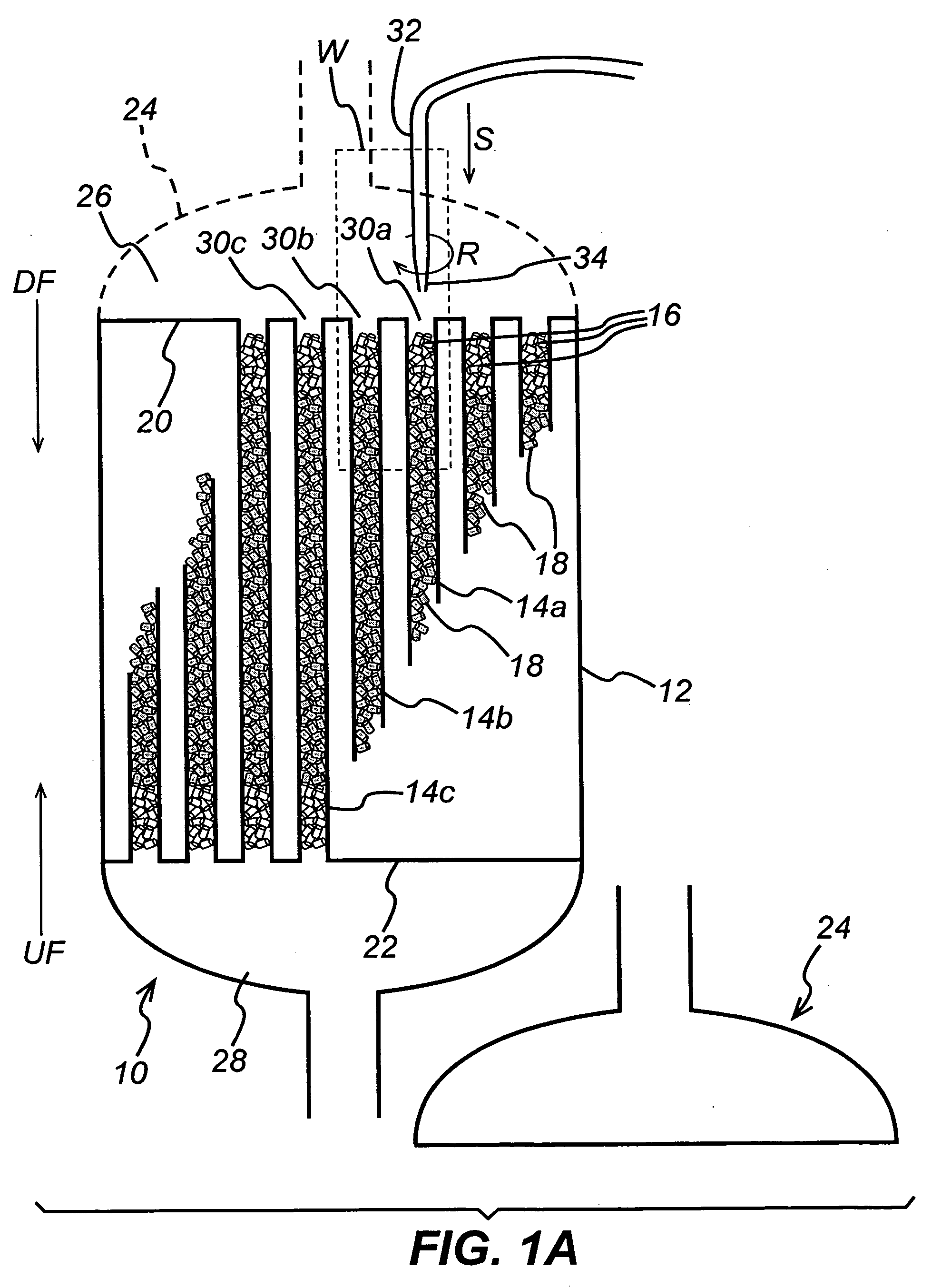
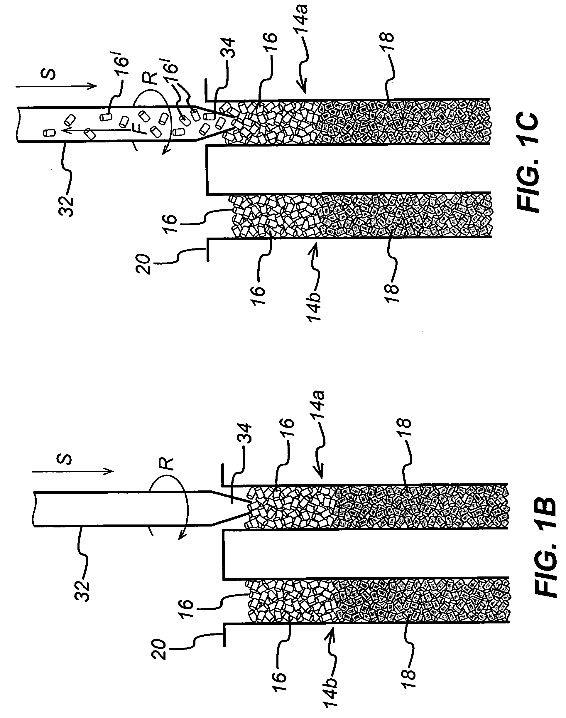
[0022]The present invention provides a method for minimizing damage to at least a portion of solid materials during dislodging and extraction of the solid materials from reactor tubes of a shell-and-tube reactor, so that at least a portion of the solid materials remain structurally suitable for re-use after dislodging and extraction. The method of the present invention comprises the steps of axially aligning a hollow rod, having a tip, with a corresponding reactor tube, and positioning the hollow rod such that the tip is proximate to the exposed end of the corresponding reactor tube and then rotating the hollow rod. The rotating hollow rod is inserted into the exposed end of the corresponding reactor tube so that its tip is in physical contact with at least a portion of the solid materials and at least a portion of the solids materials is dislodged by applying a controlled axially-directed force to the rotating hollow rod and controllably pressing the tip of the rotating hollow rod against the solid materials. The combined axially-directed force and the torsion provided by rotation of the rod dislodges even tightly wedged or bridged solid materials while minimizing damage to them so that at least at portion of them remains structurally suitable for re-use after dislodging and extraction. The method further comprises the step of extracting at least a portion of the dislodged solid material from the corresponding reactor tube by aspirating the dislodged solid materials, in a flowing fluid stream, through the hollow rod. During dislodging, the rotating and axially-directed force may be monitored and adjusted to minimize damage to at least a portion of the solid materials and ensure their structural suitability for re-use. All or only a portion of the solid materials may be dislodged and extracted from the reactor tubes.

Problems solved by technology

With time and use, the activity, or performance, of the catalyst material decreases, causing a progressive decrease in product yield until it is no longer economically feasible to continue using the catalyst material.
Clearly, the longer it takes to extract used catalyst and solids and load fresh catalyst and solids in the tubes, the more production time is lost.
Solid materials, whether catalyst or other, having non-spherical shapes are very often more difficult to remove because the particles of such materials tend to get impacted, and can, and often do, bridge, within the reactor tube and, therefore, must first be dislodged.
Solid materials may also undesirably glue, or adhere, to one another, or to the inner walls of the reactor tubes, or both due to carbonaceous deposits or other materials present (e.g., impurities introduced in the reactant streams) or formed (e.g., dimers or polymers) in the reactor during operation.
Also, the longer the reactor is operated, the more such solid materials are generated, deposited and wedged, or impacted, in the reactor tube, which of course makes them more difficult to dislodge.
Any of these situations will, of course, hinder the extraction of solid materials from the tubes because they have to be first dislodged without damaging the tubes, other parts of the reactor, and any of the solid materials which are intended to be recovered and re-used.
However, even where inert materials can be separated from other extracted solid materials, when they are wedged, adhered or bridged in the tubes, the inert materials may be physically damaged or deformed during dislodging to the extent that they are no longer structurally suitable for re-use.
Later methods and devices for removing catalyst materials and other solids from vertically-oriented reactor tubes generally involved access and removal of the solids from the bottom ends of the tubes, using fish tapes, and was extremely time-consuming, labor intensive, and unhealthy for operators (see, e.g., U.S. Pat. No. 4,994,241).
While this method enabled replacement of used catalyst materials and other solids, it also created a large amount of particulate dust which is detrimental to workplace health and safety, and it required workers to labor in awkward and uncomfortable positions for long periods of time.
Unfortunately, use of the bottom-access fish tape method for catalyst replacement in a vertically-oriented reactor necessarily resulted in extraction of all solids from each tube because removal of the bottom-most layers eliminated the support which otherwise kept upper layers in place.
This means that the remaining useful life of the slower-deactivating catalyst was always wasted because both catalysts would be removed and replaced when the faster-deactivating catalyst was exhausted.
However, if the solid materials were wedged, adhered, or bridged in the tubes, such as often occurs over time with continuous operation of the reactor, dislodging the solid materials consumes more time and they are often deformed or destroyed while being dislodged, which renders them unsuitable for re-use, even after separation and cleaning.
Unfortunately, the air lancing apparatus and methods described above all suffer from the same deficiency—they are ineffective for removing impacted solid materials (i.e., bridged, wedged, glued, adhered, etc., as described hereinabove) because the force they are able to provide for dislodging the solids is limited by the diffuse nature of the fluid stream and is often not enough to dislodge such impacted solid materials.
Axial force is applied to the tip to physically crush and destroy wedged, bridged or otherwise impacted solid materials, but the tube and tip are not rotatable and cannot provide torsional forces often necessary to dislodge strongly impacted solid materials.
This process utilizes apparatus technology analogous to that described hereinabove which employs only a vacuum and, therefore, does not disclose or suggest a method or apparatus for dislodging impacted solid materials, without damage to the reactor tube or the solid materials themselves.
Additionally, keeping track of the status of each tube during replacement of one or more solid materials is a serious challenge requiring well-organized tracking procedures which should also be simple in practice.

Method used


Image

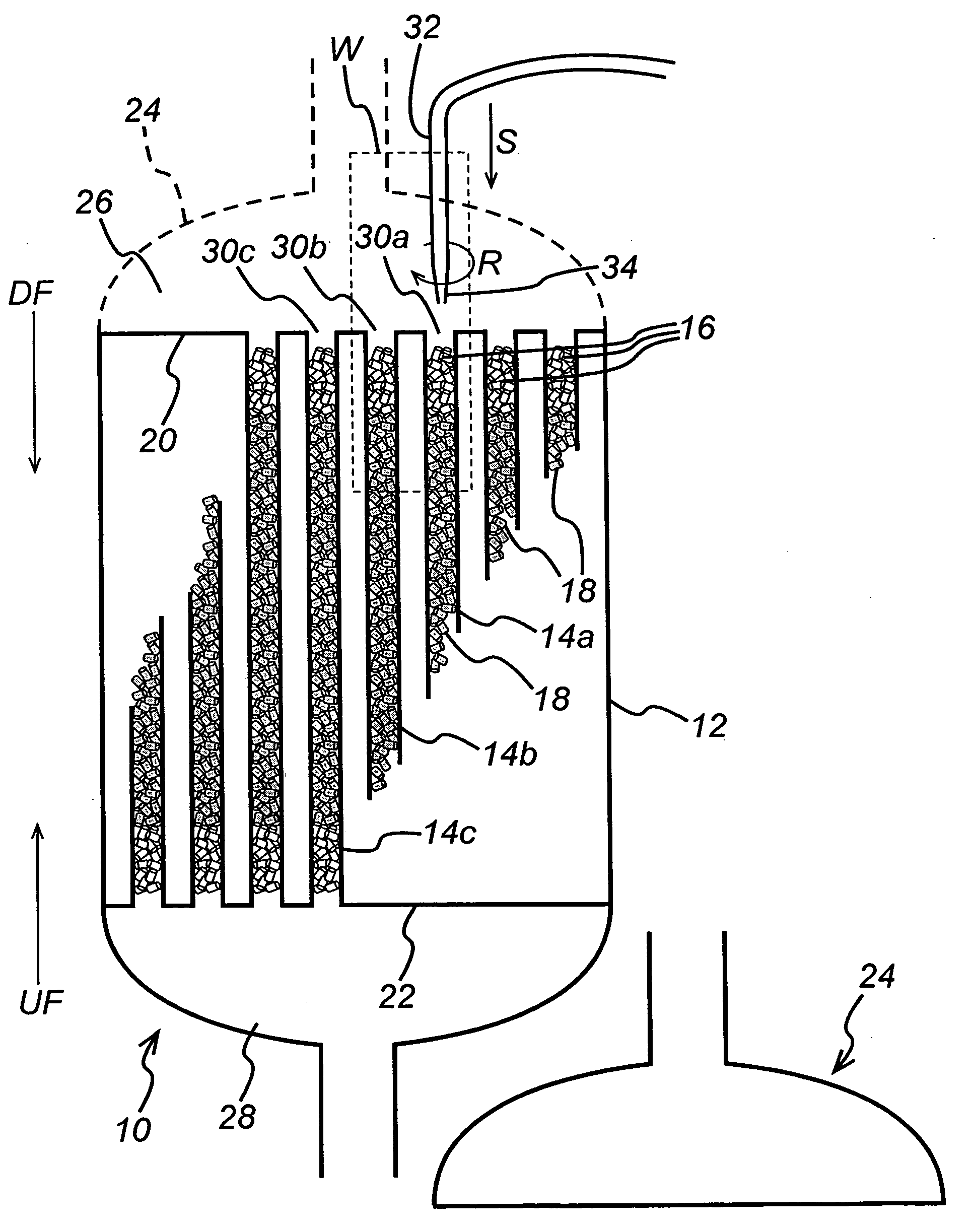
  • Apparatus and method for dislodging and extracting solid materials from tubes
  • Apparatus and method for dislodging and extracting solid materials from tubes
  • Apparatus and method for dislodging and extracting solid materials from tubes

Examples


Embodiment Construction

[0051]The method and apparatus of the present invention minimizes damage to solid materials, during dislodging and extraction of at least a portion of them from tubular members, such as the reactor tubes of shell-and-tube reactors, so that at least a portion of the extracted solid materials remain structurally suitable for re-use. The present invention also provides a method which facilitates monitoring and communicating the status of each tube during dislodging, removing, and replacing at least a portion of solid materials from reactor tubes.

[0052]The following definitions are provided to facilitate description of the present invention and clarify the terminology used hereinafter.

[0053]As used herein, the term “C2 to C5 alkane” means a straight chain or branched chain alkane, having from 2 to 5 carbons atoms per alkane molecule, for example, ethane, propane, butane and pentane. The term “C2 to C5 alkene” means a straight chain or branched chain alkene having from 2 to 5 carbons ato...


PUM


Abstract

The present invention provides an apparatus and method for efficiently dislodging and extracting at least a portion of solid materials from one or more reactor tubes of shell-and-tube reactors without damage to at least a portion of the solid materials which would otherwise render the solid materials unsuitable for re-use. The apparatus has at least one rod, a rotator assembly for rotating the rod, and a transmission assembly for applying an axially-directed force to insert the rod into a corresponding reactor tube and dislodging solid materials therein. The rod is also in fluid communication with an aspirator for extraction of dislodged solid materials. When the apparatus has more than one rod, they are arranged in a configuration matching the pattern of the reactor tubes and each rod is in axial alignment with a corresponding reactor tube. The method involves the steps of inserting one or more rods into corresponding reactor tubes, dislodging at least a portion of the solid materials, while minimizing damage to the solid materials or the tubes by rotating and applying an axially directed force to the rods as they contact the solid materials. The dislodged solid materials are then extracted from the reactor tubes. The method may further involve tracking and communicating the completed steps for each reactor tube by placing and replacing indicators on the reactor tubes, thereby enabling an operator to determine which step to perform next.

Description

[0001]This application claims the benefit of priority under 35 U.S.C. §119(e) of U.S. Provisional Patent Application No. 60 / 904,308 filed on Mar. 1, 2007.FIELD OF THE INVENTION[0002]The present invention relates to a method and an apparatus for efficiently dislodging and extracting at least a portion of solid materials from one or more reactor tubes of shell-and-tube reactors, while minimizing damage to the solid materials and leaving at least a portion of the solid materials structurally suitable for re-use. The present invention also relates to a method for monitoring and communicating the status of the tubes during the removal and replacement of the solid materials.BACKGROUND OF THE INVENTION[0003]There are situations which, for various reasons, require the removal of solid materials from tubular members without damage to the tubular members or the solid materials.[0004]For example, shell-and-tube heat exchangers are used as reactor vessels for conducting chemical reaction proces...

Claims


Application Information

Patent Timeline
Patent Type & Authority Applications(United States)
IPC IPC(8): G05B15/00B02C17/16B02C23/00
CPCB01J8/0025B01J2208/00761B01J8/06B01J8/0045B08B5/04
Inventor DECOURCY, MICHAEL STANLEYLE, NAM QUOCSWANN, SCOTT MARK
Owner DECOURCY MICHAEL STANLEY
Why Eureka
Try Eureka