
Load size measuring apparatus and method

Inactive Publication Date: 2009-04-30
GENERAL ELECTRIC CO
View PDF13 Cites 10 Cited by
  • Summary
  • Abstract
  • Description
  • Claims
  • Application Information

AI Technical Summary

Benefits of technology

[0080]Advantages to the embodiments of the present invention include that cost is reduced because various, prior art components are not required. Additionally the exemplary method of the present invention can be performed on a dry load or a wet load. Dedicated sensors are not used in the exemplary embodiments of the present invention; time and speed are measured and / or calculated, hence there is a cost reduction in materials per unit. The exemplary method of the present invention accomplishes load detection by transitioning between open and closed loop modes. The method also accomplishes the adjustment of constants “on the fly” or during the operation of the washer so that load measurement is tuned to washer settings (e.g. fabric type, user selected load size, etc.). Resolution is enhanced by lowering torque and accuracy is enhanced by repeating portions of the method multiple times. Calibration functionality for a particular washer can be part of the method stored in the washer control circuit; hence calibration is “built in” to the washer in some embodiments. The present invention can be performed in both horizontal axis and vertical axis washers, as may be determined by one of ordinary skill in the art.

Problems solved by technology

Large clothes loads require larger quantities of water than do small loads.
Too much water or detergent is wasteful, and too little of either will generally adversely affect the effectiveness of the washing, and may result in increased energy consumption due to a higher load on the motor as a result of the inability of the clothes to move freely in the water.
Prior art washing machines that use sensing hardware are costly due to the need for dedicated sensing hardware.

Method used


Image

  • Load size measuring apparatus and method
  • Load size measuring apparatus and method
  • Load size measuring apparatus and method

Examples


Embodiment Construction

Washing Machine Introduction

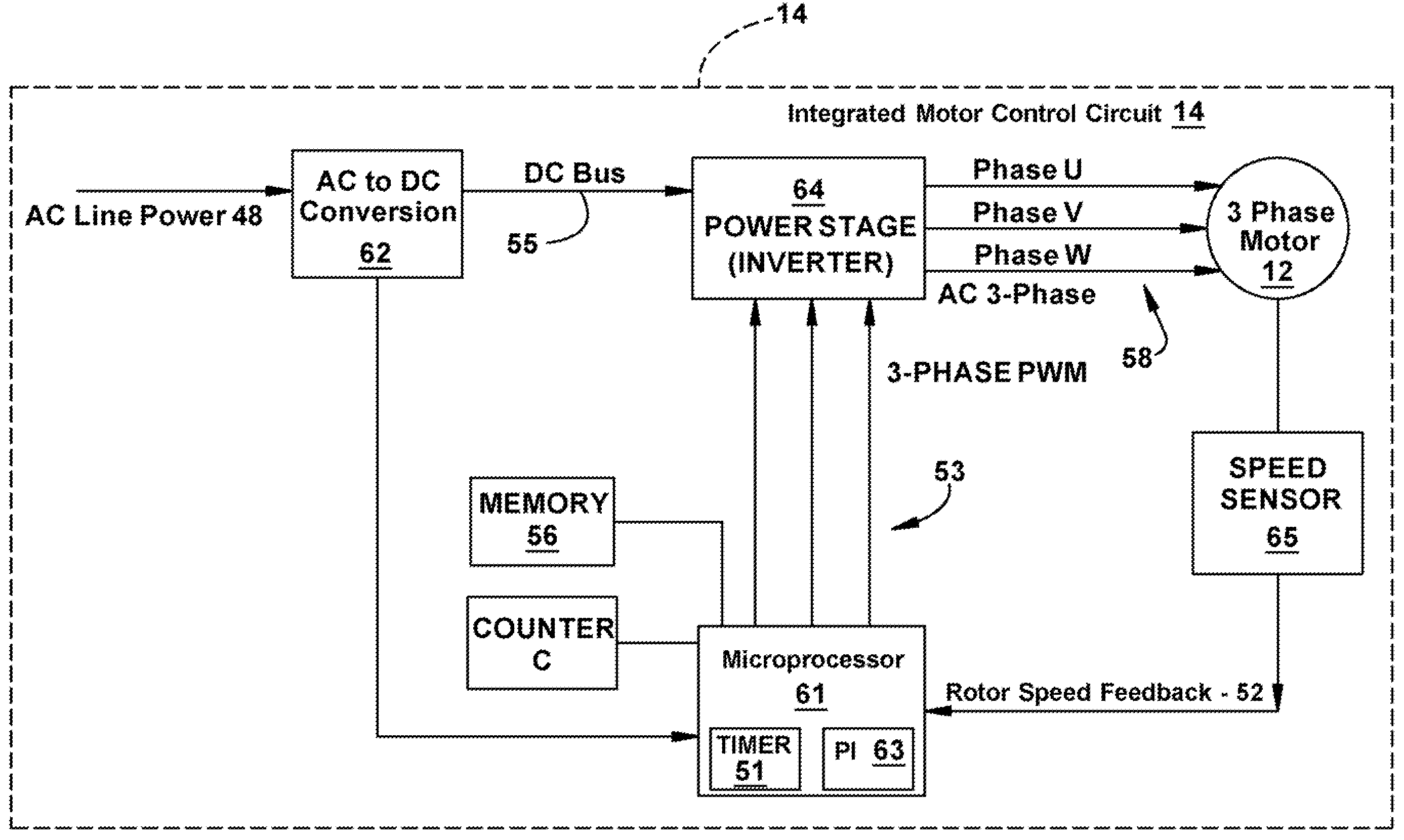
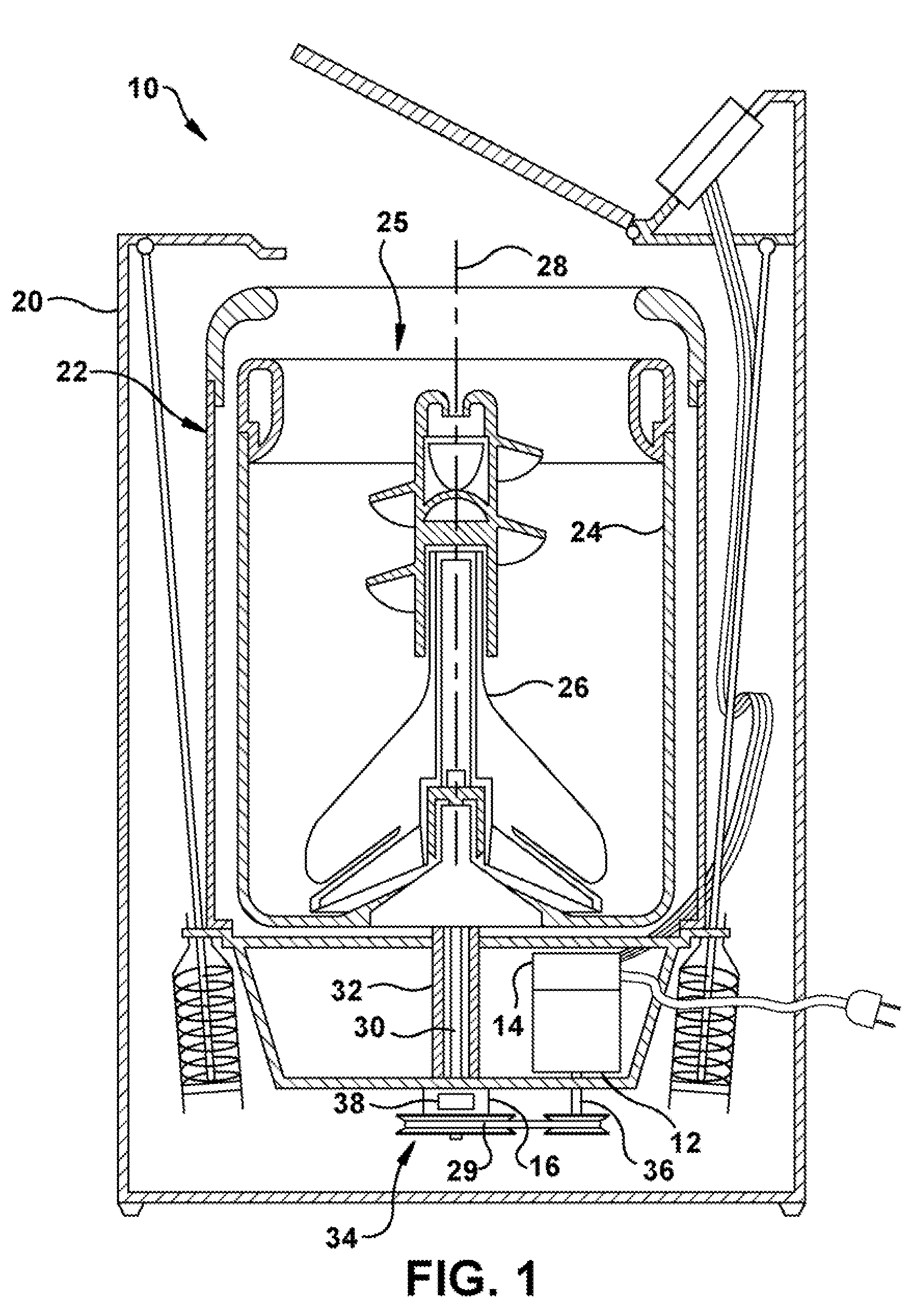
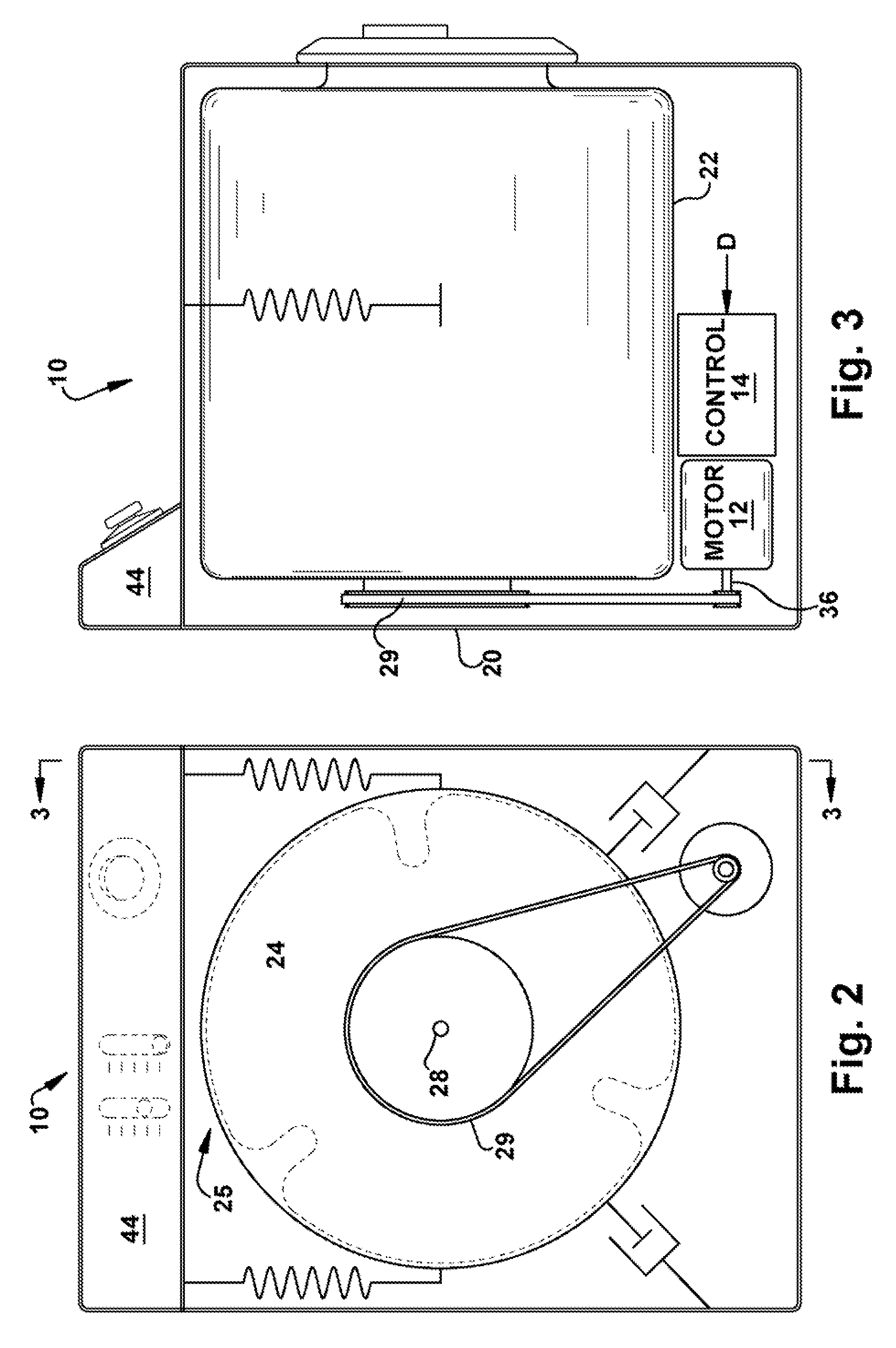
[0032]Referring to the drawings and in particular to FIG. 1, a washing machine (“washer”) according to an exemplary embodiment of the present invention is illustrated and is generally referred to by reference numeral 10. For purposes of clarity, aspects of washer 10 necessary for understanding of the present disclosure, as well as aspects helpful in understanding the operation of washer 10 are described herein. Washer 10 described herein can be a vertical axis washer 10 as is illustrated in FIG. 1 or a horizontal axis washer 10, as is illustrated in FIGS. 2 and 3. One of ordinary skill in the art can perform the exemplary embodiments of the invention described herein using either configuration. Like reference numerals are used in the horizontal and vertical axis washer illustrations.

[0033]Washer 10 includes a motor 12 and a motor control unit 14. Motor 12 is a three-phase alternating current (AC) induction motor and, in some embodiments includes motor con...


PUM


Abstract

A washing machine is provided that includes measuring a load in a washer with a motor, the method comprising: a) accelerating a load in the washer b) providing a first input voltage and running the motor until a first speed of the motor is stable; c) providing a second input voltage, d) starting a timer, upon providing the second input voltage, and obtaining a first time measurement; e) operating the motor until the load speed responds to the second input voltage to the motor and is stable; f) stopping the timer and obtaining a second time measurement; g) calculating a time differential between the first time measurement and the second time measurement; and h) determining the load size using a load size equation and the time differential.

Description

BACKGROUND OF THE INVENTION[0001]1. Field of the Invention[0002]The present disclosure is related to measuring an aspect of a load supported by a container. More particularly, the present disclosure is related to measuring a size of a load in a tub or basket that is subject to a rotational acceleration.[0003]2. Description of Related Art[0004]Vertical axis washing machines, also known as top loading washing machines, represent a large portion of the overall washing machine consumer market in the United States. Horizontal axis washing machines represent a smaller segment of the United State market and abroad typically represent a larger portion of the overall washing machine consumer market.[0005]Most vertical axis washing machines include a spin cycle for removing water and / or detergents from the laundry using centrifugal force and spinning a wash load tub, also referred to as a laundry tub (“tub”) or basket. During a typical spin cycle, the motor, typically an induction motor, of t...

Claims


Application Information

Patent Timeline
IPC IPC(8): G01G19/18D06F34/18
CPCG01G19/56D06F39/003D06F34/18D06F2103/24D06F2103/04D06F2103/38D06F2105/48D06F2103/46
Inventor FILIPPA, MARIANOHATFIELD, EDWARDKOLLIPARA, MEHER P.SUEL, II, RICHARD D.HOLMES, JOHN STEVEN
Owner GENERAL ELECTRIC CO
Learn More