Rotorcraft fitted with turbine engines

a technology of turbine engines and rotorcrafts, which is applied in the direction of rotocraft, jet propulsion plants, air transportation, etc., can solve the problems of long and expensive specific fuel consumption, long and expensive operations, and particular high power, and achieve simple, inexpensive, and compact operation. , the effect of increasing the driving power of the rotorcraft engin

Inactive Publication Date: 2009-05-07
EUROCOPTER
View PDF13 Cites 22 Cited by
  • Summary
  • Abstract
  • Description
  • Claims
  • Application Information

AI Technical Summary

Benefits of technology

[0027]The invention enables the specific consumption of a rotorcraft to be reduced while cruising.
[0028]The invention provides a system that is simple, inexpensive, and compact that enables the driving power delivered by a rotorcraft engine to be increased.

Problems solved by technology

Matching an existing helicopter to requirements / missions that require a higher level of power can be achieved to some extent and under certain circumstances by adding an engine and by modifying the power transmission mechanism accordingly; however in order to modify the transmission mechanism that requires specific design, development, and testing are required, and that is lengthy and expensive.
That technique also tends towards providing engines of lower unit power, but unfortunately their specific fuel consumption is then greater than that of engines of high unit power.
Furthermore, the design, development, and testing of an engine of suitable power, in particular of high power, are likewise operations that are lengthy and expensive.

Method used


Image

  • Rotorcraft fitted with turbine engines
  • Rotorcraft fitted with turbine engines
  • Rotorcraft fitted with turbine engines

Examples


Embodiment Construction

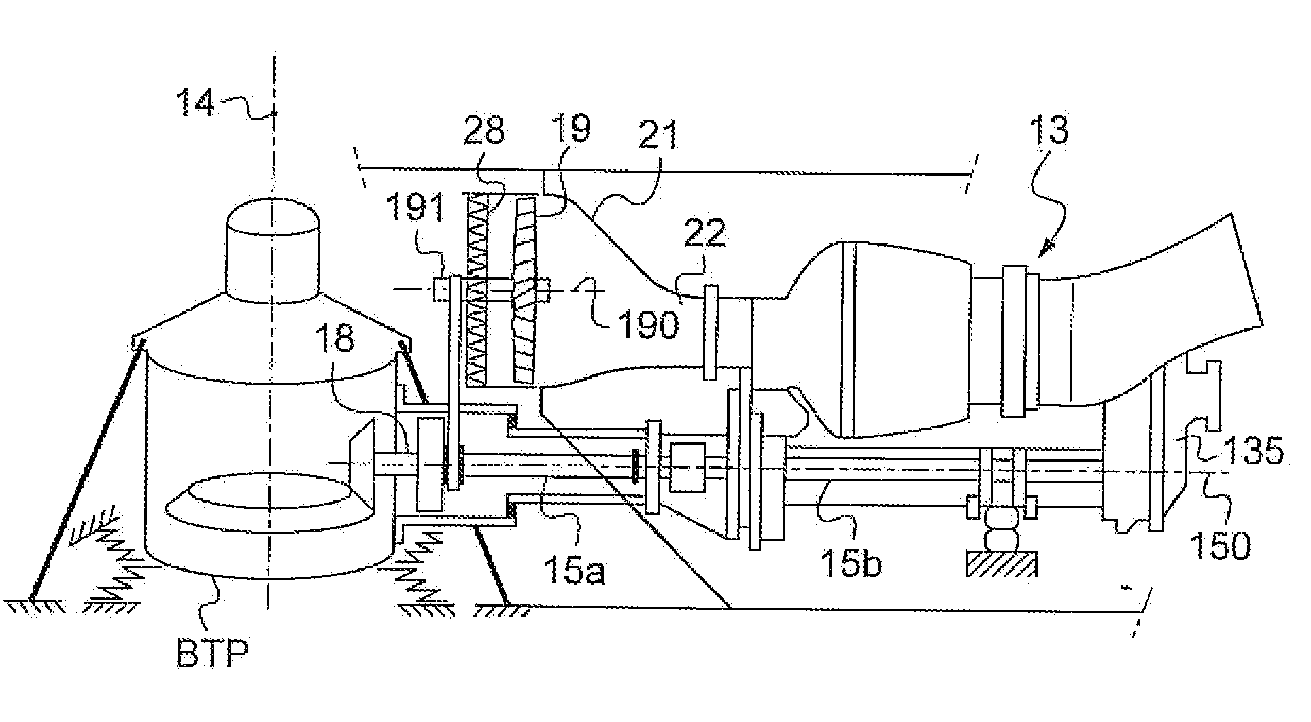
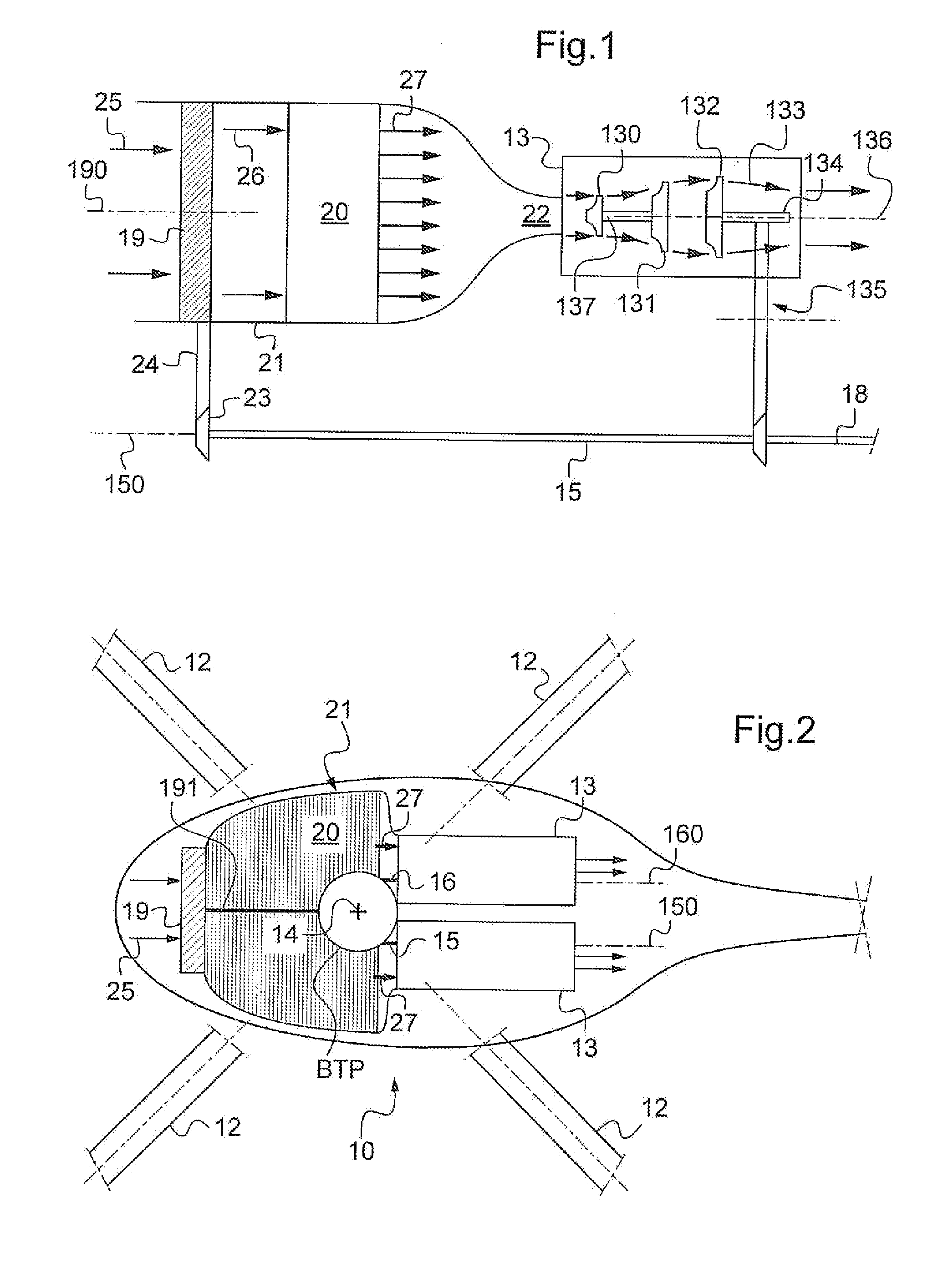
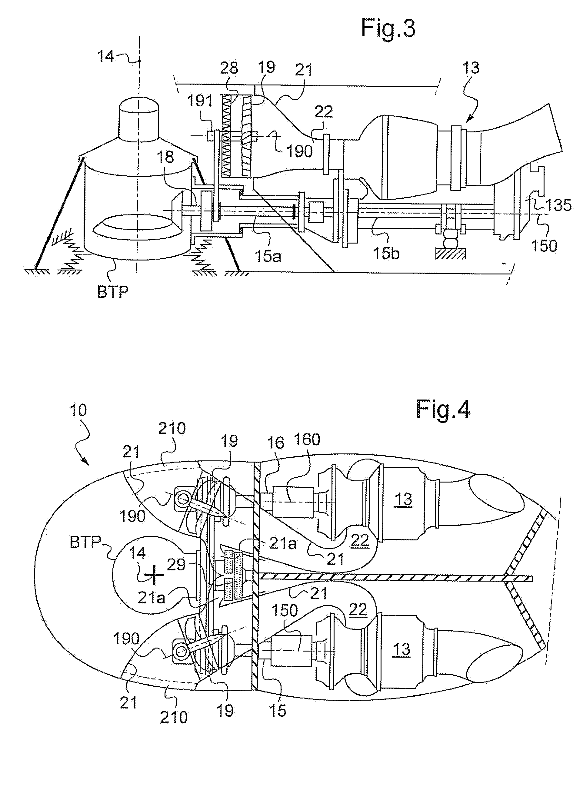
[0036]With reference to FIGS. 2 to 6, the invention relates to helicopters 10 and other rotorcraft in which at least one lift and propulsion rotor 11 having blades 12 is driven in rotation about a substantially vertical axis 14 by one or more turbine engines 13.

[0037]A main gearbox (MGB) acts to connect an outlet shaft 15, 16 from each engine to the shaft 17 of the main rotor, this gearbox including in particular a speed reducer (cf. FIG. 5).

[0038]As shown in FIG. 1, each engine comprises an internal compressor 130 and a first turbine 131 constrained to rotate with the internal compressor 130. The engine also includes a free turbine 132 that is located downstream from the first turbine relative to the direction 133 in which gas flows through the engine.

[0039]The free turbine produces driving torque that is transmitted by the shaft 134 of the free turbine and then via a speed reducer 135 and by an outlet shaft 15 of the engine that extends beside and outside the engine, along an axis...


PUM


Abstract

The invention relates to a rotorcraft (10) having a main rotor (11), a turbine engine (13), and a transmission mechanism (MGB) coupled to the rotor and to the engine to enable the engine to drive the rotor. The engine has a free turbine (132) connected to the transmission mechanism (MGB) by a shaft (15, 15a, 15b, 16, 18). The rotorcraft includes an external compressor (19) arranged to be driven by the free turbine (132) or by an electric motor, together with an air-transport duct (21) connecting the external compressor (19) to the engine so as to deliver the air that has been compressed by the external compressor to the inlets (22) of the engine.

Description

[0001]The present invention relates to improvements provided to rotorcraft fitted with one or more turbine engines.[0002]The technical field of the invention is that of helicopter manufacture.BACKGROUND OF THE INVENTION[0003]A rotorcraft has at least one rotor fitted with blades, sometimes referred to as the main rotor, that serves on being rotated to provide the rotorcraft with lift and propulsion.[0004]A rotorcraft also has one, two, or three engines serving to drive the main rotor, and possibly an anti-torque rotor, and also various accessories (alternator and pump(s) in particular).[0005]A transmission mechanism, also known as a main gearbox (MGB) acts to connect an outlet shaft from the engine to the shaft of the main rotor, the transmission mechanism including in particular a speed reducer. Such mechanisms are described by way of example in patents U.S. Pat. No. 3,002,710, U.S. Pat. No. 3,255,825, and U.S. Pat. No. 4,811,627.[0006]Each engine has an axial and / or centrifugal co...

Claims


Application Information

Patent Timeline
Patent Type & Authority Applications(United States)
IPC IPC(8): F02C3/04
CPCB64C27/12B64D27/10B64D33/02B64D35/02F05D2220/329F02C7/143F02C7/36Y02T50/675F02C3/103Y02T50/60B64C27/18
Inventor CERTAIN, BERNARD
Owner EUROCOPTER
Why Eureka
Try Eureka