Electrospray source

a technology of electrolyte and source, which is applied in the direction of machine/engine, vessel construction, marine propulsion, etc., can solve the problems of large shower head and bulky, and achieve the effect of reducing manufacturing cost and facilitating manufactur

Active Publication Date: 2009-05-07
BUSEK
View PDF9 Cites 15 Cited by
  • Summary
  • Abstract
  • Description
  • Claims
  • Application Information

AI Technical Summary

Benefits of technology

[0010]It is a further object of this invention to provide a novel electrospray source which is easier to manufacture and which can be manufacture...

Problems solved by technology

Also, the showerhead...

Method used


Image

  • Electrospray source
  • Electrospray source
  • Electrospray source

Examples


Embodiment Construction

[0034]Aside from the preferred embodiment or embodiments disclosed below, this invention is capable of other embodiments and of being practiced or being carried out in various ways. Thus, it is to be understood that the invention is not limited in its application to the details of construction and the arrangements of components set forth in the following description or illustrated in the drawings. If only one embodiment is described herein, the claims hereof are not to be limited to that embodiment. Moreover, the claims hereof are not to be read restrictively unless there is clear and convincing evidence manifesting a certain exclusion, restriction, or disclaimer.

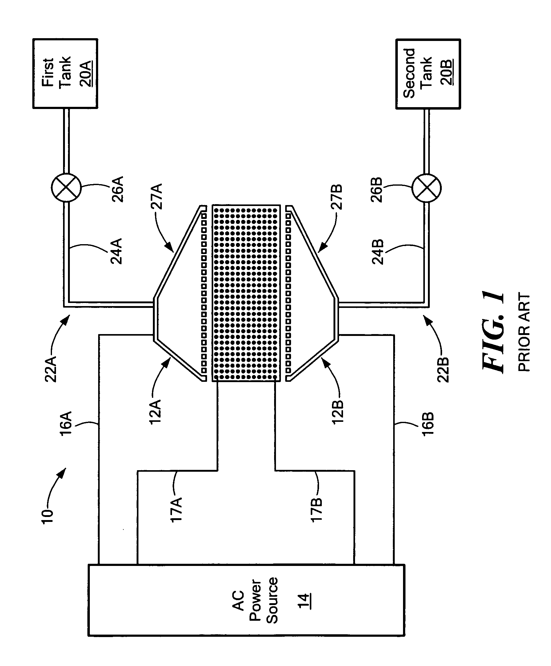
[0035]FIG. 1 depicts a prior electromagnetic thruster 10 in accordance with U.S. Pat. No. 6,996,972. As disclosed in the patent, electromagnetic thruster 10 is useful for positioning and translating a spacecraft in space. Thruster 10 includes showerheads 12A and 12B, power source 14, magnetic field generator 18, two tanks 2...


PUM


Abstract

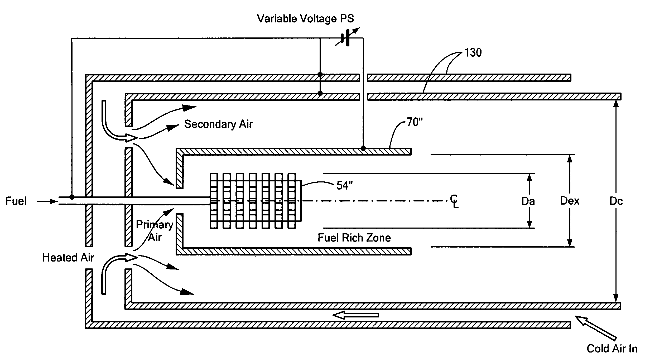
An electrospray source useful for a variety of applications and including an emitter with a porous media flow distributor having a surface forming multiple Taylor cones. A casing about the porous media flow distributor controls the direction of a working fluid through the porous media. An extractor is at a potential different than the emitter for forming the Taylor cones. A guard electrode is disposed between the emitter and the extractor and is at or above the potential of the emitter for shaping the electric field formed between the emitter and the extractor.

Description

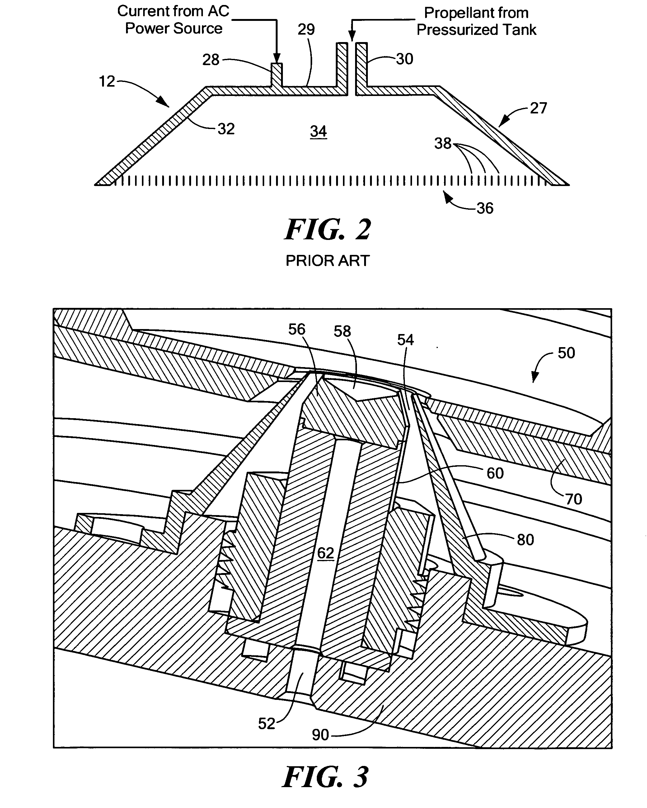
RELATED APPLICATIONS[0001]This application hereby claims the benefit of and priority to U.S. Provisional Application Ser. No. 60 / 965,664, filed on Aug. 21, 2007 incorporated herein by this reference.GOVERNMENT RIGHTS[0002]This invention was made with U.S. Government support under Contract No. FA9300-04-M-3102 awarded by the U.S. Air Force. The Government has certain rights in the invention.FIELD OF THE INVENTION[0003]The subject invention relates to electrospray technology.BACKGROUND OF THE INVENTION[0004]Electrospray sources are used in a variety of applications. U.S. Pat. No. 6,996,972 (incorporated herein by this reference), for example, discloses an electromagnetic spacecraft thruster with two showerheads each producing multiple jets. Each showerhead includes hundreds of micro-nozzles. Each micro-nozzle includes a conductive metallic layer coated with a thin insulative layer to form a frustum-shaped or conic truncated apex tip outlet resulting in a jet-producing Taylor cone of p...

Claims


Application Information

Patent Timeline
IPC IPC(8): F03H99/00
CPCB05B5/0255F03H1/0012B05B5/0533
Inventor DEMMONS, NATHANIELHRUBY, VLADSPENCE, DOUGLASROY, THOMAS
Owner BUSEK
Why Eureka
Try Eureka