

Solar Collector and Mounting Bracket
a technology for mounting brackets and solar collectors, which is applied in the direction of solar heat collector mounting/support, solar heat collector safety, and solar heat collectors with working fluids, etc., can solve problems such as tension, and achieve the effect of reliable and flexibl
- Summary
- Abstract
- Description
- Claims
- Application Information
AI Technical Summary
Benefits of technology
Problems solved by technology
Method used
Image

Examples
Embodiment Construction
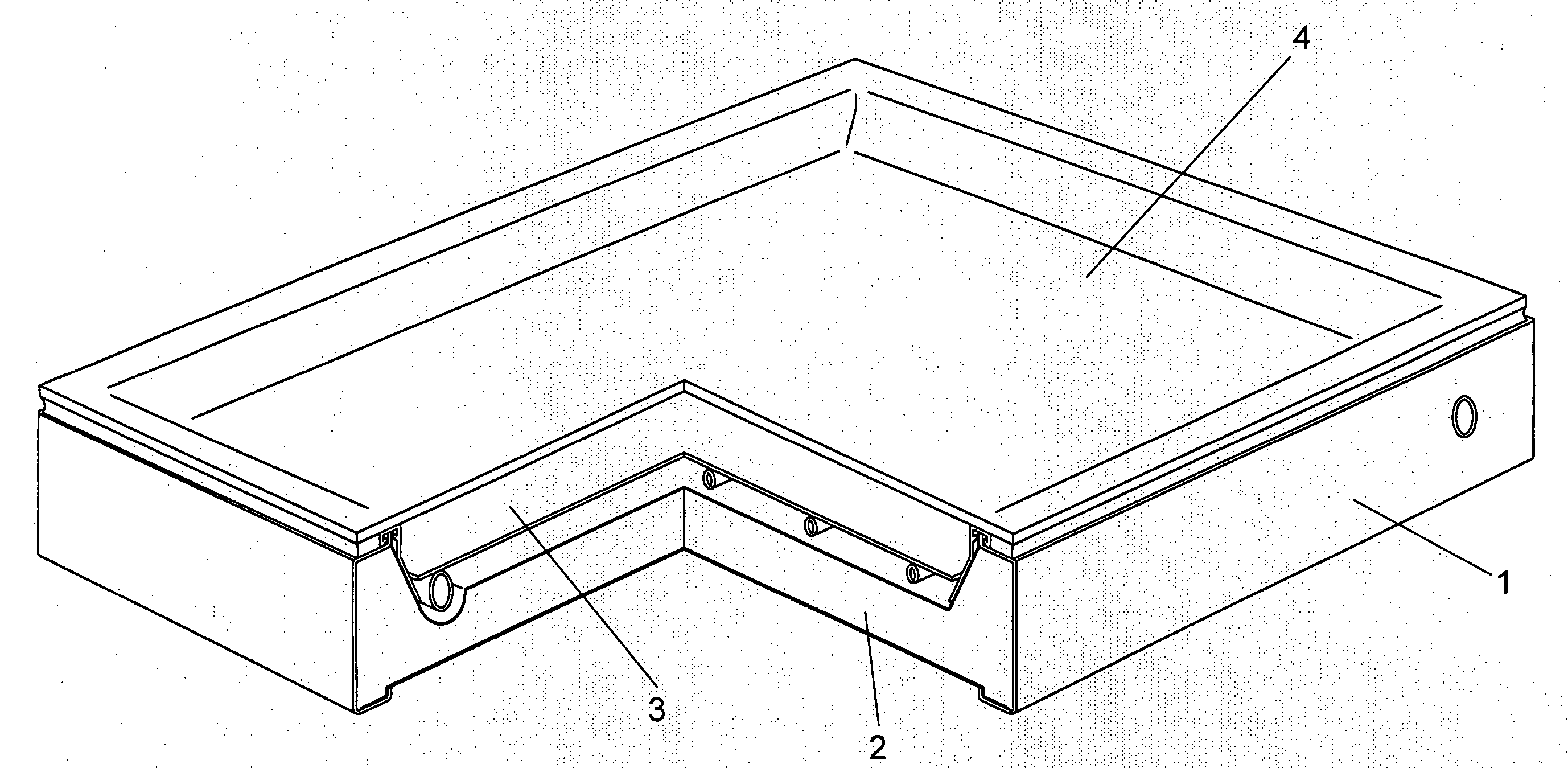
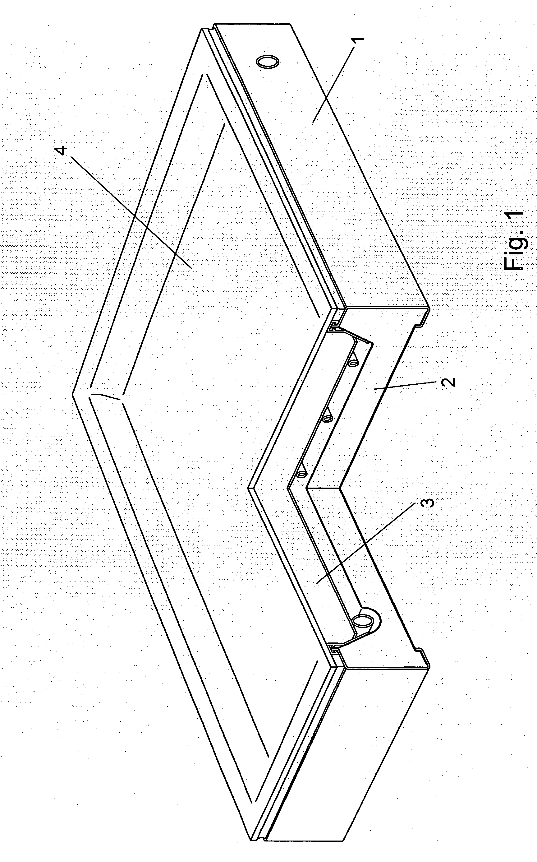
[0030]A preferred embodiment of the invention will be described specifically with reference to a flat plate collector assembly although it is understood that other absorber types may be employed with a minimum change in construction.
[0031]FIG. 1 shows by way of illustrative example a flat plate solar energy collector. Seen in cutaway perspective view of FIG. 1 the solar collector has a frame 1, an insulation layer 2, an absorber plate 3 and a cover pane 4. The frame, the insulation layer and the cover pane form a case with an enclosure. The enclosure is used to provide support for the absorber, and to protect the collector from heat loss due to wind, plus the important function of keeping moisture from rain, snow and dew out of the collector.
[0032]The insulation layer 2 is made of a rigid foam urethane (PUR) or polyisocyanurate (PIR). These materials have an excellent insulation value per unit of thickness and are easy to handle because they are very light. They have also a higher c...
PUM
 Abstract
Description
Claims
Application Information