
Portable gas shock or air bag inflator or deflator

a gas shock or air bag technology, applied in the field of gas shocks or air bags, can solve the problems of flammable gasses, xenon or helium, more expensive gasses, etc., and achieve the effect of low cost and low weigh

Inactive Publication Date: 2009-05-07
RUBICON MFG
View PDF3 Cites 11 Cited by
  • Summary
  • Abstract
  • Description
  • Claims
  • Application Information

AI Technical Summary

Benefits of technology

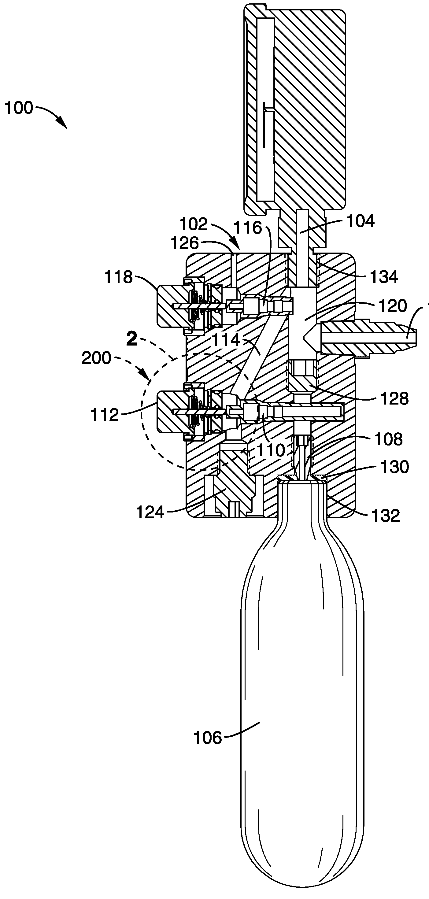
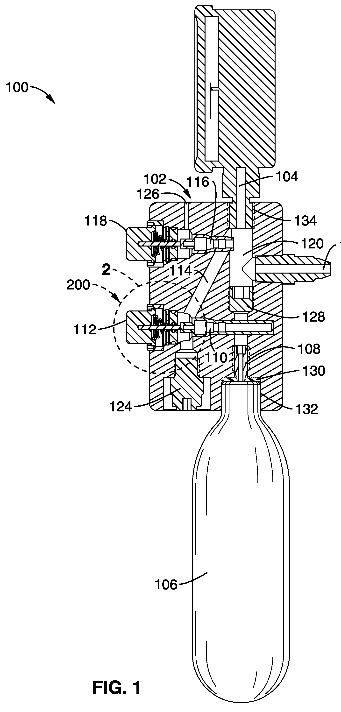
[0009]An aspect of the invention is a hand held apparatus for pressurizing gas shocks or air bags, comprising: an object to be pressurized; and a means for pressurizing the object. The object to be pressurized may comprise a gas shock, an air bag, or other component requiring accurate fill pressures, such as tires or other pneumatic leveling devices. Additionally, brake lines may be pressurized to assist in brake bleeding procedures.
[0023]The manifold may be comprised of a composition selected from a group of materials consisting essentially of: aluminum; fiberglass; a thermoplastic; and a thermoset plastic. The thermoplastic and thermoset plastics may both be foamed plastics when a foaming agent is added. Although aluminum is a likely choice of metals to use, other metals, such as copper, tin, steels, or titanium may be used, the only limitation being difficulties in fabrication and material cost. For ease of machining, low cost, and low weight, it is difficult to prefer any of the other alternative metals over aluminum.

Problems solved by technology

Nothing in this application precludes pressurization by other, more expensive gasses such as Xenon or Helium, or flammable gasses, such as hydrogen or methane.

Method used


Image

  • Portable gas shock or air bag inflator or deflator
  • Portable gas shock or air bag inflator or deflator
  • Portable gas shock or air bag inflator or deflator

Examples


Embodiment Construction

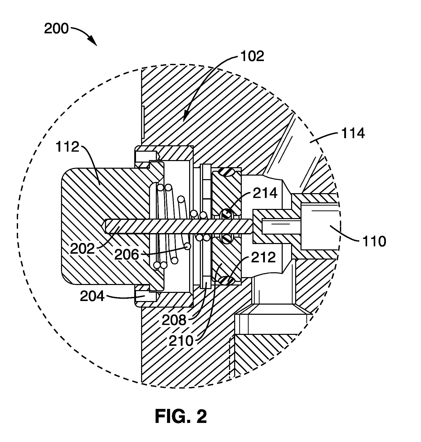
[0033]Referring more specifically to the drawings, for illustrative purposes the present invention is embodied in the apparatus generally shown in FIG. 1 through FIG. 4B. It will be appreciated that the apparatus may vary as to configuration and as to details of the parts, and that the method may vary as to the specific steps and sequence, without departing from the basic concepts as disclosed herein.

[0034]Pneumatic devices that provide lift and shock absorbing capacity are widely used world-wide. Frequently, these devices are filled with nitrogen gas, as this is substantially non-reactive relative to the materials (usually some sort of rubber) exposed to the gas. Dry air may be used, but it suffers from increase reactivity, hence oxidation. Simple compressed air suffers from the moisture that is ubiquitous in the atmosphere. Where non-dry air is used, reactivity may be increased over that of dry air, and the moisture may change state from gas to liquid or even solid, greatly changi...


PUM


Abstract

An apparatus for hand held inflating or deflating gas shocks or air bags is disclosed that is substantially hand held. A body comprises a high pressure valve, a lower pressure vent valve, and a pressurized plenum between the two valves. A high pressure gas source is connected tot the high pressure valve on one side. An object to be pressurized is connected to the other side to the lower pressure pressurized plenum. A gage is optionally available to monitor the pressure of the object to be pressurized. This device, which may fit into traditionally glove compartments and tool boxes, allows for quick and accurate pressurization of gas filled devices with pressure tunable characteristics. Although described here with a standalone highly pressurized gas source, a standard pressure disconnect can allow the device to be used with conventional tire inflation and deflation with an external pump supplying the high pressure source.

Description

CROSS-REFERENCE TO RELATED APPLICATIONS[0001]This patent application claims benefit of priority to U.S. provisional patent application 60 / 982,424, filed Oct. 25, 2007, which is hereby incorporated by reference in its entirety.STATEMENT REGARDING FEDERALLY SPONSORED RESEARCH OR DEVELOPMENT[0002]Not ApplicableINCORPORATION-BY-REFERENCE OF MATERIAL SUBMITTED ON A COMPACT DISC[0003]Not ApplicableBACKGROUND OF THE INVENTION[0004]1. Field of the Invention[0005]This invention pertains generally to gas shocks or air bags, more particularly to conveniently pressurized gas shocks or air bags, and still more particularly to devices for readily changing the pressure in pressurized devices.[0006]2. Description of Related Art[0007]Gas filled shock absorbers, and air bags, are used to vary the riding conditions of a vehicle under large changes in loading conditions. Typically, changing the pressures in these devices is not easy, as one must find nitrogen or another gas source, and apply this press...

Claims


Application Information

Patent Timeline
IPC IPC(8): F03B11/00
CPCF17C13/04Y02E60/321F17C2201/058F17C2205/0146F17C2205/032F17C2205/0323F17C2205/0385F17C2221/011F17C2221/012F17C2221/014F17C2221/016F17C2221/017F17C2221/033F17C2221/038F17C2223/0123F17C2223/035F17C2250/043F17C2250/0491F17C2260/012F17C2270/0168F17C2270/0772F17C2201/0109Y10T137/8593Y02E60/32
Inventor WALLACE, RYAN
Owner RUBICON MFG
Learn More