Method of stimulating a well

Active Publication Date: 2009-05-07
TOTAL E&P DANMARK AS
View PDF26 Cites 35 Cited by
  • Summary
  • Abstract
  • Description
  • Claims
  • Application Information

AI Technical Summary

Benefits of technology

[0027]If the acid or aggressive fluid is pumped into a tubular with pre-fabricated perforations where the perforations are placed with an even distribution along the tubular, the acid will flow into the formation where the most open structure of the formation occurs, causing the self-perpetuating effect mentioned above. A tubular with few perforations may lead t

Problems solved by technology

Pre-perforated liners may have an even distribution of perforations (number of perforations per unit length), but the use of such liners may suffer from the same d

Method used


Image

  • Method of stimulating a well
  • Method of stimulating a well
  • Method of stimulating a well

Examples


Embodiment Construction

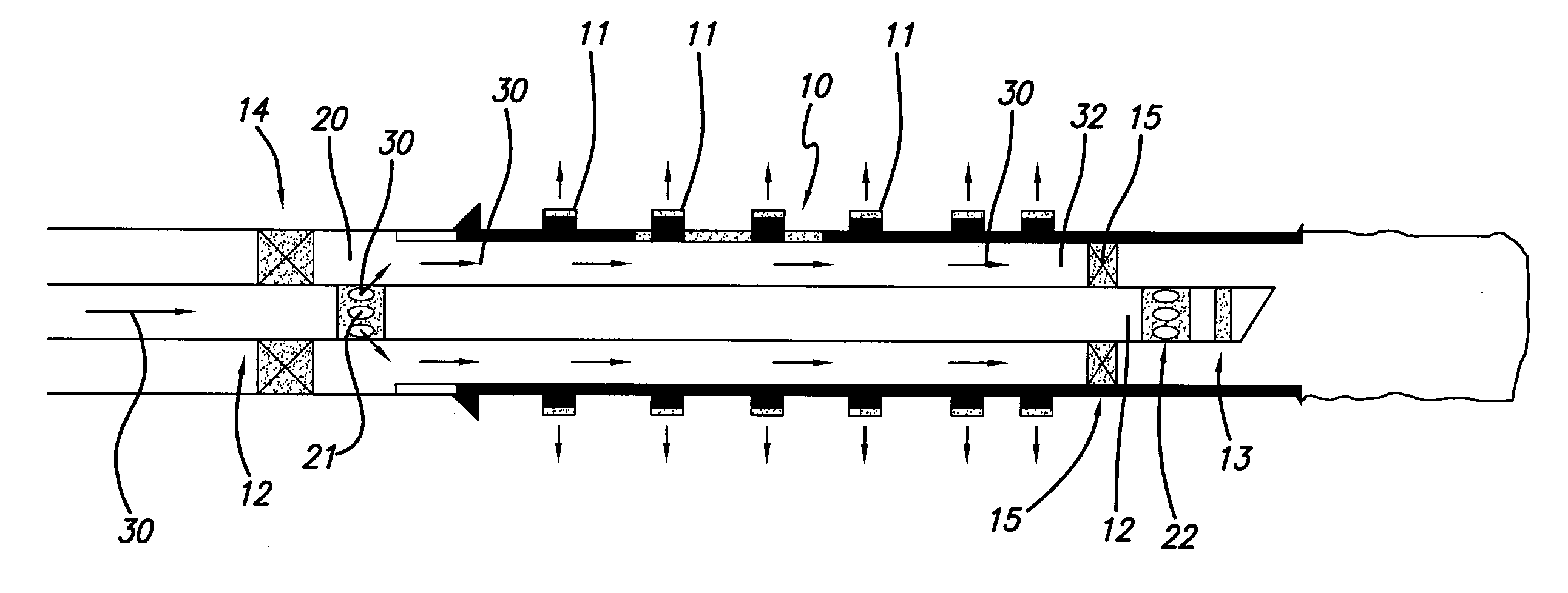
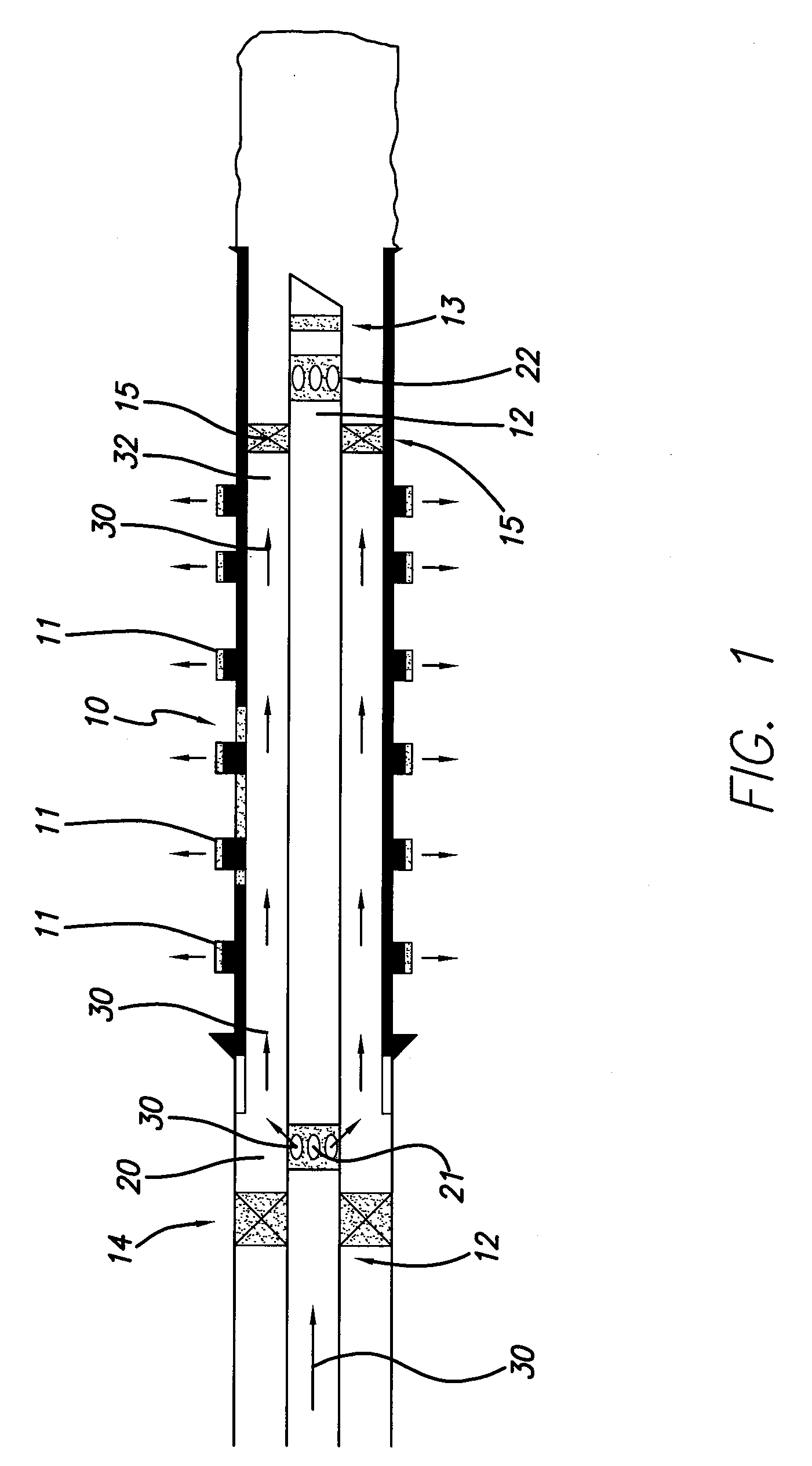
[0068]FIG. 1 shows a tubular 10 for production from or for stimulating a well for use in the purpose of production of hydrocarbons from a formation 1 or from a surrounding of a formation 1.

[0069]Production of oil commonly uses tubulars in support of the well or distribution of fluid or both. The tubular 10 shown in FIG. 1 in the form of a cemented liner, is provided with perforations 11 for distribution of fluid from either the formation 1 and into the wellbore or from the wellbore and out to the formation 1.

[0070]Inside the tubular 10, a tubing 12 is provided. The tubing 12 comprises a plug 13 at a free end preventing the fluid from flowing out of the end. Outside the tubing 12 and between the tubing 12 and the wellbore and / or the cemented liner 10, packers 14, 15 are placed. The purpose of the packers 14, 15 is to provide a zone 20 between the packers 14, 15, where the zone 20 is isolated from the rest of the wellbore.

[0071]The tubing 12 is further provided with closable openings ...


PUM


Abstract

A tubular introduced into a wellbore is perforated at pre-selected locations after the tubular has been cemented into place. The locations of the perforations are determined by modeling inflow performance of a stimulation fluid within the formation. The inflow performance parameters include reservoir porosity, permeability, pressure, damage skin and intrusion depth, perforation diameter and penetration depth or perforation crushed zone damage and intrusion depth.

Description

RELATED APPLICATIONS[0001]The present patent document claims the benefit of the filing date under 35 U.S.C. § 119(e) of Provisional U.S. Patent Application Ser. No. 60 / 975,348, filed 26 Sep. 2007, and the benefit of priority to Danish Patent Application No. PA 200701385, filed 26 Sep. 2007, the entirety of each of which are incorporated herein by reference.BACKGROUND[0002]1. Technical Field[0003]The invention relates to a method of stimulating a drilled and cemented well for use in the production of hydrocarbons from a formation, when acid or an aggressive liquid is introduced through a perforated tubular for dissolving material.[0004]2. Related Art[0005]In related art, a cemented tubular, such as a casing or liner, may be perforated with an even density (number of perforations per unit length), and an improvement in stimulation fluid distribution may be attempted by changing the fluid characteristics, the injection rate or injection of dissolvable materials that temporarily seals o...

Claims


Application Information

Patent Timeline
IPC IPC(8): E21B43/16E21B17/00
CPCE21B43/28
Inventor LUMBYE, PETER
Owner TOTAL E&P DANMARK AS
Why Eureka
Try Eureka