Drive device of vehicle

a technology of driving device and hybrid vehicle, which is applied in the direction of dc-ac conversion without reversal, structural association, gearing, etc., can solve the problems of difficult standardization of parts, insufficient consideration of reducing the space required for mounting the drive device on the hybrid vehicle, and complicated structure, etc., to achieve small and simple structure

Inactive Publication Date: 2009-05-07
TOYOTA JIDOSHA KK
View PDF15 Cites 35 Cited by
  • Summary
  • Abstract
  • Description
  • Claims
  • Application Information

AI Technical Summary

Benefits of technology

[0007]An object of the invention is to provide a vehicle drive device which includes an integrated converter and has a small and simple structure.
[0017]The invention can achieves the vehicle drive device that is integrated with an inverter and has a small and simple structure.

Problems solved by technology

Therefore, it is difficult to standardize parts.
However, in the drive devices of the hybrid vehicles disclosed in Japanese Patent Laying-Open Nos. 2004-343845 and 2001-119961, the inverter is merely arranged on the motor, and this structure is susceptible to improvement in connection with a vertical position of the center of mass of the vehicle equipped with the device.
Further, consideration is not sufficiently given to reduction of a space required for mounting the drive device on the hybrid vehicle.
In Japanese Patent Laying-Open No. 2003-199293, a water-cooling system is employed as a cooling system of an inverter unit, and an oil-cooling system is employed as a cooling system of a motor unit so that the structure is complicated.

Method used


Image

  • Drive device of vehicle
  • Drive device of vehicle
  • Drive device of vehicle

Examples


Embodiment Construction

[0034]Embodiments of the invention will now be described with reference to the drawings. The same or corresponding portions bear the same reference numbers, and description thereof is not repeated.

[0035][Description of Vehicle Components]

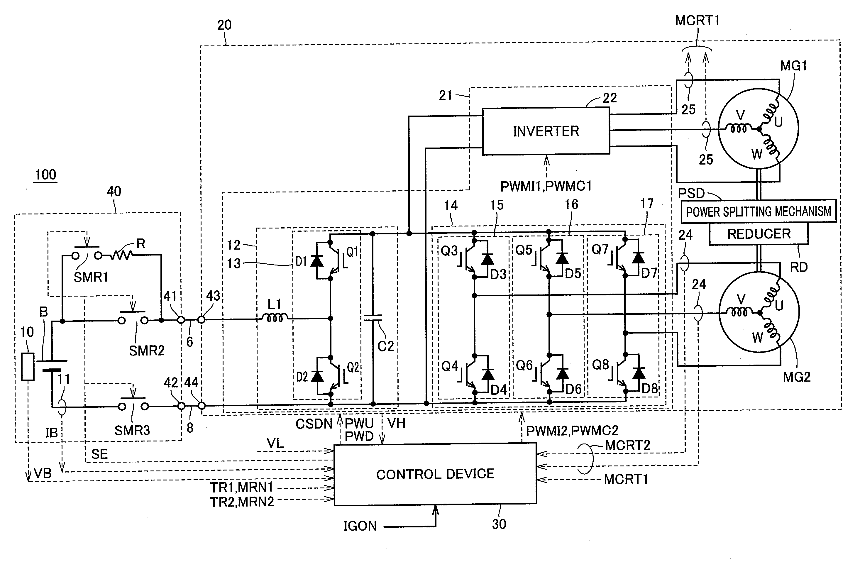
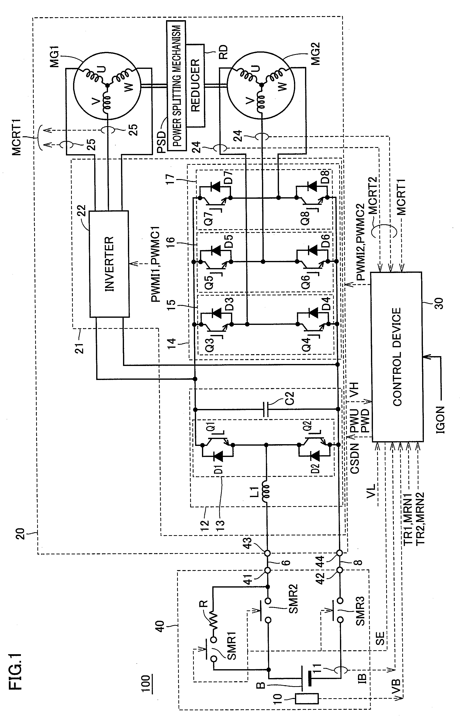
[0036]FIG. 1 is a circuit diagram showing a structure relating to a motor generator control of a hybrid vehicle 100 according to the embodiment of the invention.

[0037]Referring to FIG. 1, vehicle 100 includes a battery unit 40, a drive device 20 and a control device 30 as well as an engine and wheels that are not shown.

[0038]Drive device 20 includes motor generators MG1 and MG2, a power splitting mechanism PSD, a reducer RD and a power control unit 21 controlling motor generators MG1 and MG2.

[0039]Basically, power splitting mechanism PSD is connected to an engine 4 and motor generators MG1 and MG2 for distributing a power between engine 4 and motor generators MG1 and MG2. For example, a planetary gear mechanism having three rotation axes, i.e., a su...


PUM


Abstract

A drive device of a vehicle includes a motor generator, a lubricant circulating mechanism lubricating and cooling the motor generator, a power control unit controlling the motor generator, arranged on a circulation path of a lubricating oil and being in contact with the lubricating oil for transferring and receiving a heat to and from the lubricating oil, and a casing accommodating the motor generator, the lubricating mechanism and the power control mechanism, and provided with the circulation path. Preferably, the power control unit includes a power control element and a board (120) having a first main surface on which the power control element is mounted. The board (120) is provided on its second main surface side with a radiator fin (390, 392 and 394) for contact with the lubricating oil in the circulation path.

Description

TECHNICAL FIELD[0001]The invention relates to a drive device, and particularly to a vehicle drive device accommodating an inverter and a motor in one casingBACKGROUND ART[0002]Many of present hybrid cars have structures in which an inverter has a large box-like casing fixed to a chassis, and a motor casing (trans-axle) is arranged under the casing. Consideration may be given to the drive device of the hybrid vehicle that can be mounted in as many as types of hybrid vehicles. In this case, if the device employs two casings, an arrangement of such casings must be optimized for each of the vehicle types. Therefore, it is difficult to standardize parts.[0003]In principle, it is desired that units combined with each other for the operation are integrated and accommodated in one casing. Japanese Patent Laying-Open Nos. 2004-343845, 2001-119961 and 2003-199293 have disclosed drive devices of hybrid vehicles each having a motor and an inverter integrated together.[0004]However, in the drive...

Claims


Application Information

Patent Timeline
Patent Type & Authority Applications(United States)
IPC IPC(8): B60K11/02B60K6/26B60K6/40B60K6/405B60K6/445B60L50/16B60W10/08B60W20/00F16H48/10H02K5/20H02K9/02H02K11/00H02M7/48
CPCB60K1/02Y10S903/904B60K6/365B60K6/405B60K6/445B60K2001/003B60W10/08B60W20/00F16H3/727F16H57/0457F16H57/0475F16H57/0476F16H2037/0866F16H2200/2007H02K7/116H02K9/19H02K11/046H02K11/048Y02T10/6239B60K6/26Y02T10/62H02K11/05B60K11/04B60K6/24
Inventor TAHARA, YASUAKIENDO, YASUHIROTATEMATSU, KAZUTAKA
Owner TOYOTA JIDOSHA KK
Why Eureka
Try Eureka