Strain amplification devices and methods

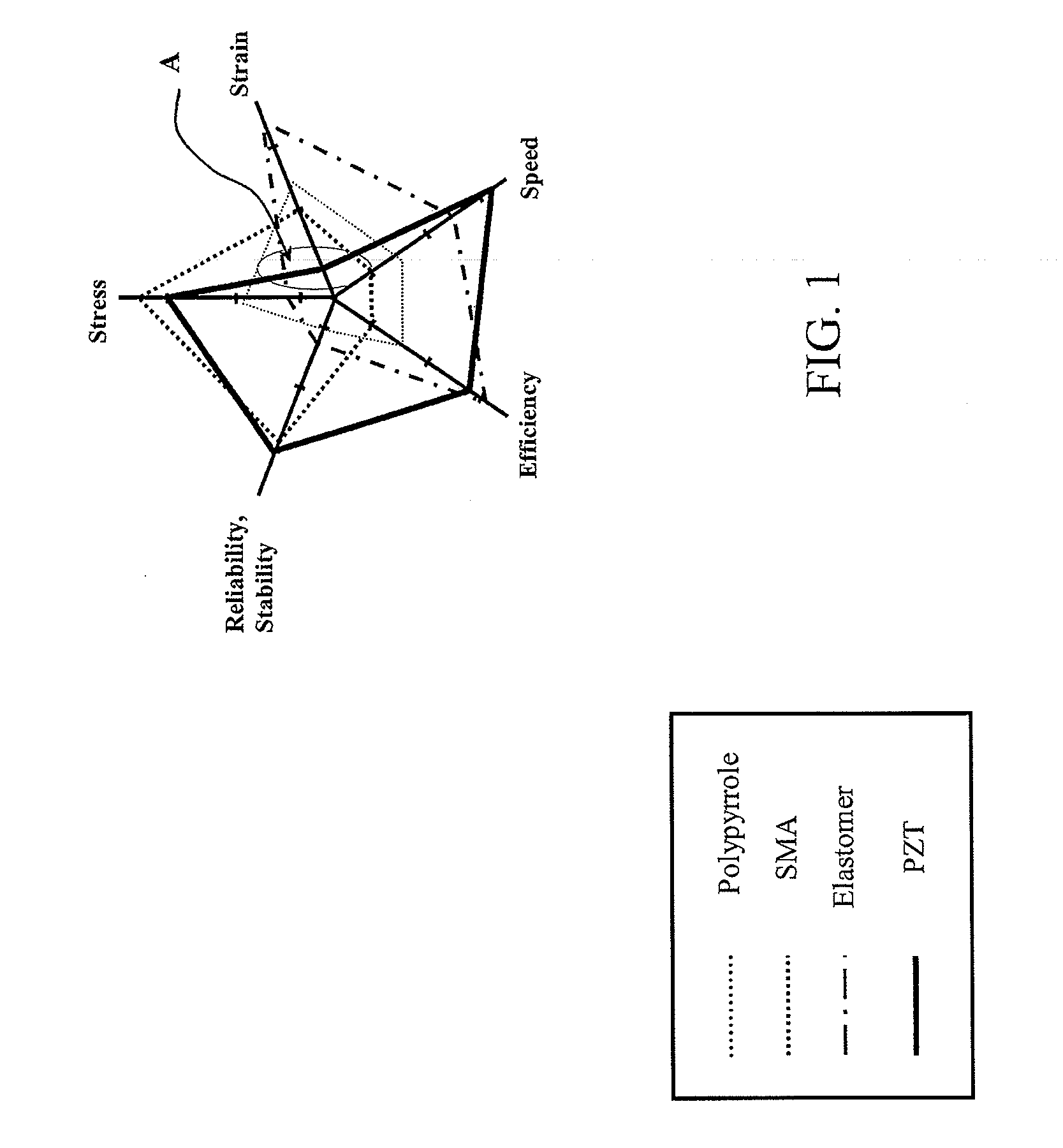
a technology of amplification devices and strains, applied in piezoelectric/electrostrictive/magnetostrictive devices, piezoelectric/electrostriction/magnetostriction machines, electrical apparatus, etc., can solve the problem of hysteresis, pzt is extremely small strain, and polypyrrole-conducting polymers degrade quickly, etc. problem, to achieve the effect of significantly greater strain

Inactive Publication Date: 2009-05-07
MASSACHUSETTS INST OF TECH
View PDF10 Cites 60 Cited by
  • Summary
  • Abstract
  • Description
  • Claims
  • Application Information

AI Technical Summary

Benefits of technology

[0013]Accordingly, a feature of the present invention is to provide devices and methods that comprise a hierarchical cellular structure for providing strain amplification, thereby achieving strain that is significantly greater than conventional strain amplification devices and methods. Another feature of the present invention is to build a modular structure that is flexible and extensible.

Problems solved by technology

Polypyrrole-conducting polymers, on the other hand, degrade quickly despite their attractive features such as relatively high stress.
A first drawback of PZT is its extremely small strain, as shown in section A of FIG. 1.
A second drawback of PZT is hysteresis.
The inherently small strain of PZT, i.e., approximately 0.1%, can be a major issue for broad applications.
However, inching motion entails friction drive, which limits its applicability to a class of applications.
Bimetal-type mechanisms, for example, described in K. Seffen and E. Toews, “Hyperthetical Actuators: Coils and Coiled-Coils,” incorporated by reference above, can produce only small forces despite their large displacement and strain, which also limit applications to small loads.
Leverage-type motion amplification, for example, described in U.S. Pat. No. 4,435,666 incorporated by reference above, is inefficient, producing only a marginal gain on the order of 10.
Systems incorporating leverage-type motion amplification tend to be bulky and heavy if several leverages are connected together to produced a larger displacement.
Although the “Moonie” strain amplification methods described above, in particular, with regard to U.S. Pat. No. 4,999,819 and U.S. Pat. No. 6,411,009, are known to be relatively efficient methods, the resulting expected amplification gain produced by the Moonie is less than 20, resulting in less than a 2% effective strain.
However, these methods likewise tend to be bulky and heavy, since the amplification gain produced by the actuators is only proportional to the dimension of the stacked layers.
However, this stacking also increases the size of the overall mechanism and does not improve the strain itself, which is limited to 2-3%, e.g., by conventional flextensional mechanisms.

Method used


Image

  • Strain amplification devices and methods
  • Strain amplification devices and methods
  • Strain amplification devices and methods

Examples


Embodiment Construction

[0085]Hereinafter, aspects of the present invention will be described by describing illustrative embodiments in accordance therewith, with reference to the attached drawings. While describing these embodiments, detailed descriptions of well-known items, functions, or configurations are typically omitted for conciseness.

[0086]It will be understood that, although the terms first, second, etc. are be used herein to describe various elements, these elements should not be limited by these terms. These terms are used to distinguish one element from another, but not to imply a required sequence of elements. For example, a first element can be termed a second element, and, similarly, a second element can be termed a first element, without departing from the scope of the present invention. As used herein, the term “and / or” includes any and all combinations of one or more of the associated listed items.

[0087]The terminology used herein is for the purpose of describing particular embodiments o...


PUM


Abstract

A multi-layer strain-amplification device includes at least one first amplifying layer unit and a second amplifying layer unit positioned about the at least one first amplifying layer unit. A strain of the at least one first amplifying layer unit is amplified by the second amplifying layer unit.

Description

RELATED APPLICATIONS[0001]This application claims the benefit of U.S. Provisional Patent Application No. 61 / 000,365, filed Oct. 25, 2007, the content of which is incorporated herein by reference in its entirety.FIELD OF THE INVENTION[0002]The invention relates to strain amplification devices and methods, specifically to multi-layer strain amplification devices and methods having hierarchical nested structures and comprising piezoelectric materials.BACKGROUND OF THE INVENTION[0003]The demand for high-force and compact actuators with large strain is increasing in robotics. Piezoelectric (PZT) ceramic material, such as lead zirconium titanate, is known as one of the promising materials used in actuators because of its high power density, high bandwidth, and high efficiency.[0004]FIG. 1 is a chart illustrating a comparison of characteristics between PZT and other materials used to form actuators. As shown in FIG. 1, PZT outperforms other actuator materials, such as shape memory alloy (S...

Claims


Application Information

Patent Timeline
Patent Type & Authority Applications(United States)
IPC IPC(8): H01L41/113
CPCH02N2/043
Inventor UEDA, JUNASADA, HARUHIKO HARRYSECORD, THOMAS WILLIAM
Owner MASSACHUSETTS INST OF TECH
Why Eureka
Try Eureka