Eureka AIR delivers breakthrough ideas for toughest innovation challenges, trusted by R&D personnel around the world.

Backlight unit, liquid crystal display apparatus having the same, and method thereof

Inactive Publication Date: 2009-05-07
SAMSUNG ELECTRONICS CO LTD
View PDF7 Cites 6 Cited by
  • Summary
  • Abstract
  • Description
  • Claims
  • Application Information

AI Technical Summary

Benefits of technology

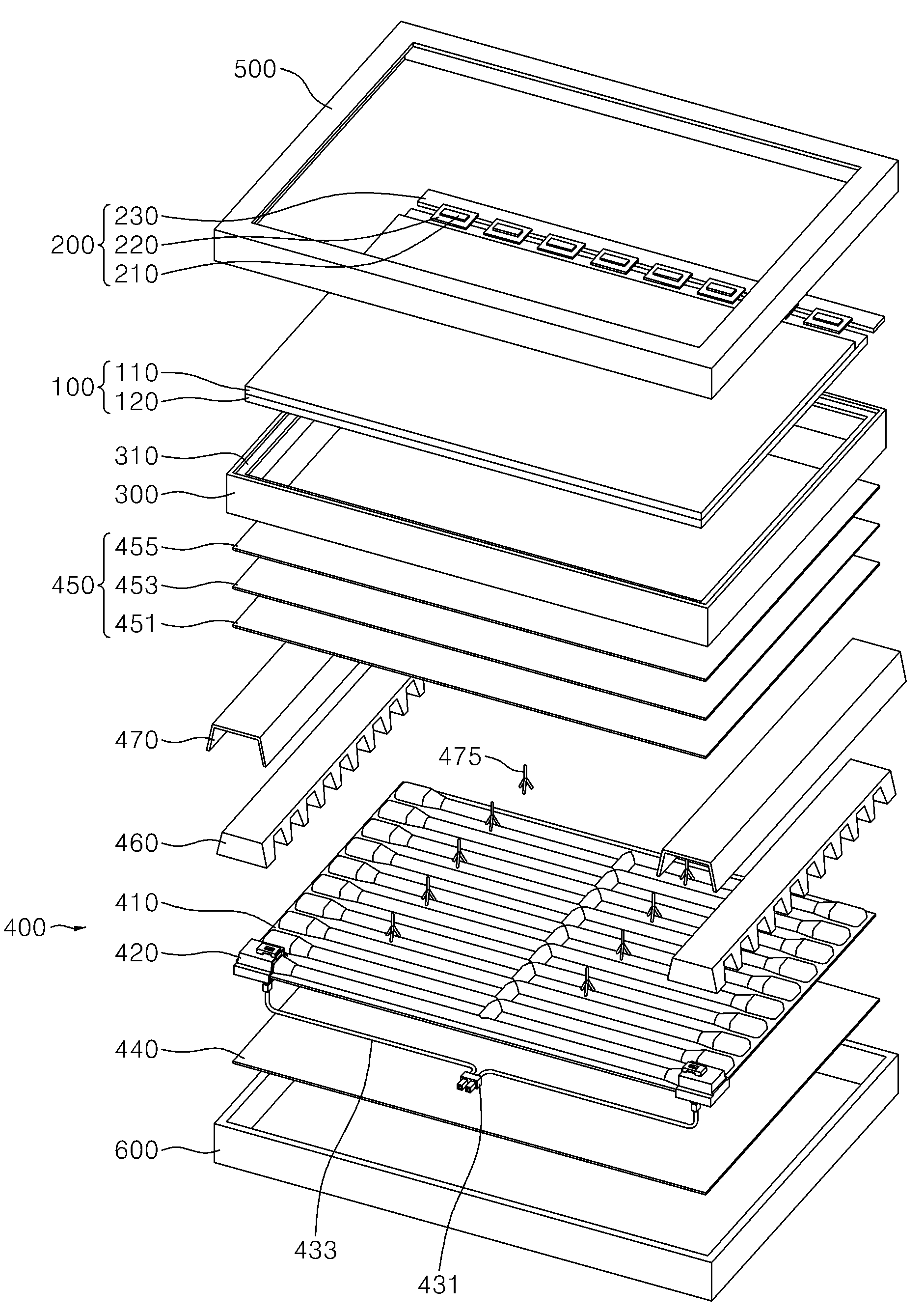
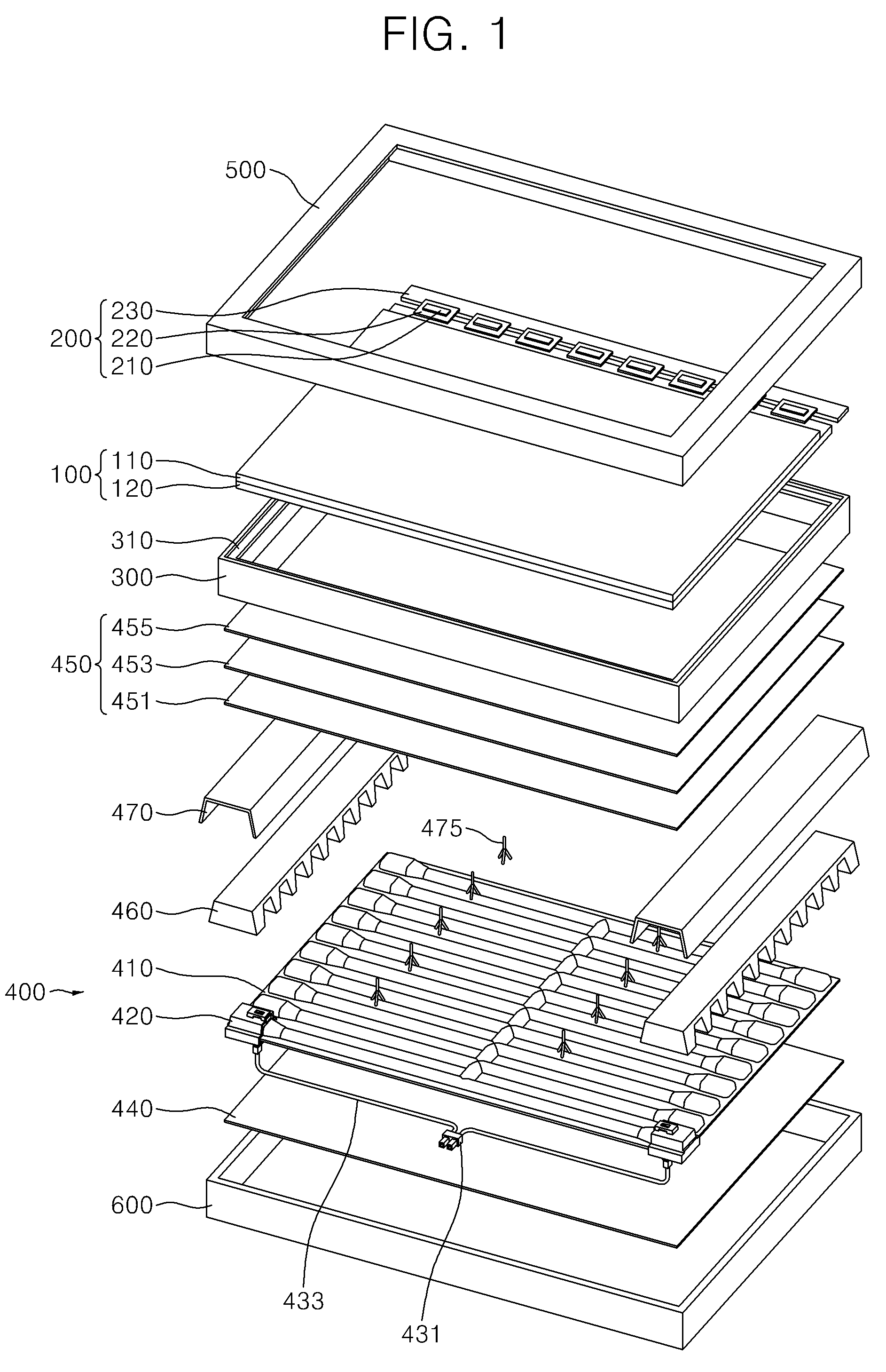
[0010]Exemplary embodiments of the present invention provide a backlight unit having a voltage source connection structure capable of reducing a manufacturing cost thereof and enhancing a light source quality by eliminating the soldering process.
[0030]An exemplary embodiment of the LCD apparatus includes socket for providing electric power to the light source. Therefore, a manufacturing cost thereof may be reduced and the manufacturing process thereof may be simplified by eliminating the soldering process.
[0031]An exemplary embodiment of the LCD apparatus protects the light source from heat and compression which were applied to the light source through the conventional soldering process by using the socket. Therefore, the LCD apparatus reduces progressive malfunctions to enhance display quality.

Problems solved by technology

Since a direct illumination type backlight unit employs a planar light source having an external electrode, there are difficulties in manufacturing the backlight unit with a wire-pressing and soldering structure for being electrically connected to an external voltage source.
For example, a soldering process and automated equipment for the soldering process are required for the manufacturing of the backlight unit, which undesirably enhances a manufacturing cost thereof.
Furthermore, in the soldering process, micro cracks may be formed due to high temperature, and terminals may not be perfectly connected with each other by the solder, which disadvantageously deteriorates a quality of the backlight unit.

Method used


Image

  • Backlight unit, liquid crystal display apparatus having the same, and method thereof
  • Backlight unit, liquid crystal display apparatus having the same, and method thereof
  • Backlight unit, liquid crystal display apparatus having the same, and method thereof

Examples


Embodiment Construction

[0039]Detail operations and exemplary embodiments of the invention are described more fully hereinafter with reference with the accompanying drawings. The present invention may, however, be embodied in many different forms and should not be construed as limited to the exemplary embodiments set forth herein. Rather, these embodiments are provided so that this disclosure will be thorough and complete, and will fully convey the scope of the invention to those skilled in the art. In the drawings, the size and relative sizes of layers and regions may be exaggerated for clarity.

[0040]It will be understood that when an element or layer is referred to as being “on” or “connected to” another element or layer, the element or layer can be directly on or connected to another element or layer or intervening elements or layers. In contrast, when an element is referred to as being “directly on” or “directly connected to” another element or layer, there are no intervening elements or layers present...


PUM


Abstract

A backlight unit includes planar light source and light source socket. The planar light source includes upper and lower plates combined with each other and forming a light emitting space therebetween, and external electrodes disposed on surface of one of the upper and lower plates. The light source socket is disposed on a portion of the external electrodes. The light source socket includes a body, a power applying member and a fixing member. The body covers the portion of the external electrode. The power applying member is disposed inside of the body and contacts the external electrode in order to apply electric power to the planar light source. The fixing member fastens the power applying member to the external electrode such that the power applying member makes contact with the external electrode.

Description

[0001]The present application claims priority to Korean Patent Application No. 10-2007-110335, filed on Oct. 31, 2007, and all the benefits accruing therefrom under 35 U.S.C. §119, the contents of which is incorporated herein by reference in its entirety.BACKGROUND OF THE INVENTION[0002]1. Field of the Invention[0003]The present invention relates to a backlight unit and a liquid crystal display (“LCD”) apparatus including the backlight unit. More particularly, the present invention relates to a backlight unit improving a voltage source connection structure, and an LCD apparatus including the backlight unit.[0004]2. Description of the Related Art[0005]Various electronic devices such as a cellular phone, a digital camera, a notebook computer, a monitor, etc., include a display apparatus. Various display apparatuses may be employed, but a flat panel display (“FPD”) apparatus is normally used.[0006]An LCD apparatus, which is a representative FPD apparatus, displays images by using elect...

Claims


Application Information

Patent Timeline
IPC IPC(8): G02F1/13357G02F1/1333H01J9/00
CPCG02F1/133604G02F1/133608H01J65/046H01J5/50H01J61/305G02F2001/133612G02F1/133612G02F1/1335H01J61/30
Inventor BAEK, KI-HWANCHUN, JAE-HWANWON, JONG-HOPARK, HYUN-SULEE, JAE-SANG
Owner SAMSUNG ELECTRONICS CO LTD
Why Eureka
Eureka Blog
Learn More