Electrolyte membrane for fuel cell

a fuel cell and electrolyte technology, applied in the field of electrolyte membrane for fuel cells, can solve the problems of shortening the service life of electrolyte, occurrence of heat-induced creep or thermal shrinkage, and insufficient proton conductivity value by itsel

Inactive Publication Date: 2009-05-07
NAT UNIV CORP SHIZUOKA UNIV +1
View PDF4 Cites 28 Cited by
  • Summary
  • Abstract
  • Description
  • Claims
  • Application Information

AI Technical Summary

Benefits of technology

[0013]The present invention provides an electrolyte membrane in which dimensional changes caused by water and heat balance variations are inhibited by mixing a proton conductive material that maintains proton conduction capacity, without losing mechanical properties and shape.
[0015]In the electrolyte membrane for a fuel cell of such a configuration, in the proton conductive material contained in the electrolyte membrane, a very large number of proton conductive groups as the end groups of the electrolyte resin filled up into the cavities of the inorganic fine particles serving as outer shells of the proton conductive material are exposed from the through-holes being located on the surface of inorganic fine particles, thereby ensuring high proton conductivity. Furthermore, because the electrolyte resin is confined in inorganic fine particles of fixed particle size, no swelling or contraction of the proton conductive material occurs. Therefore, in the electrolyte membrane, dimensional changes caused by water and heat balance are inhibited. In addition, even when a state with a high flowability is assumed such that normally occurs where a large number of proton conductive groups are introduced into the electrolyte resin structure, because the electrolyte resin is retained in the cavities of inorganic fine particles according to the embodiment, both the shape retention ability and proton conductivity of the proton conductive material are increased. Furthermore, by using a non-proton conductive polymer that demonstrates no water-induced swelling or contraction as a binder resin for film formation, dimensional changes caused by water and heat balance can be inhibited even more effectively. Because the non-proton conductive polymer is not limited to a specific polymer, the degree of freedom in polymer selection is high and a polymer of an appropriate type can be selected, thereby making it possible to obtain an optimum electrolyte membrane according to the application and object of fuel cell.

Problems solved by technology

Dimensional changes such as expansion and contraction of the membrane during water absorption and desorption and the occurrence of heat-induced creep or thermal shrinkage is a problem associated with such polymer conductive materials.
In the operation environment of fuel cells, the water and heat balance is known to change frequently due to a load or external environment, and dimensional changes of the membrane caused by such changes can shorten the electrolyte service life.
This is one more very serious problem associated with the presently available polymer conductive materials of an organic polymer type.
However, as compared with Nafion, which is an organic polymer of related art, the proton conductivity value is by itself insufficient under operation conditions (temperature, humidity) at which the power generation efficiency is the best for a fuel cell.

Method used


Image

  • Electrolyte membrane for fuel cell
  • Electrolyte membrane for fuel cell
  • Electrolyte membrane for fuel cell

Examples


Embodiment Construction

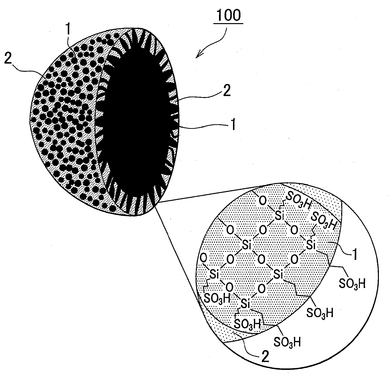
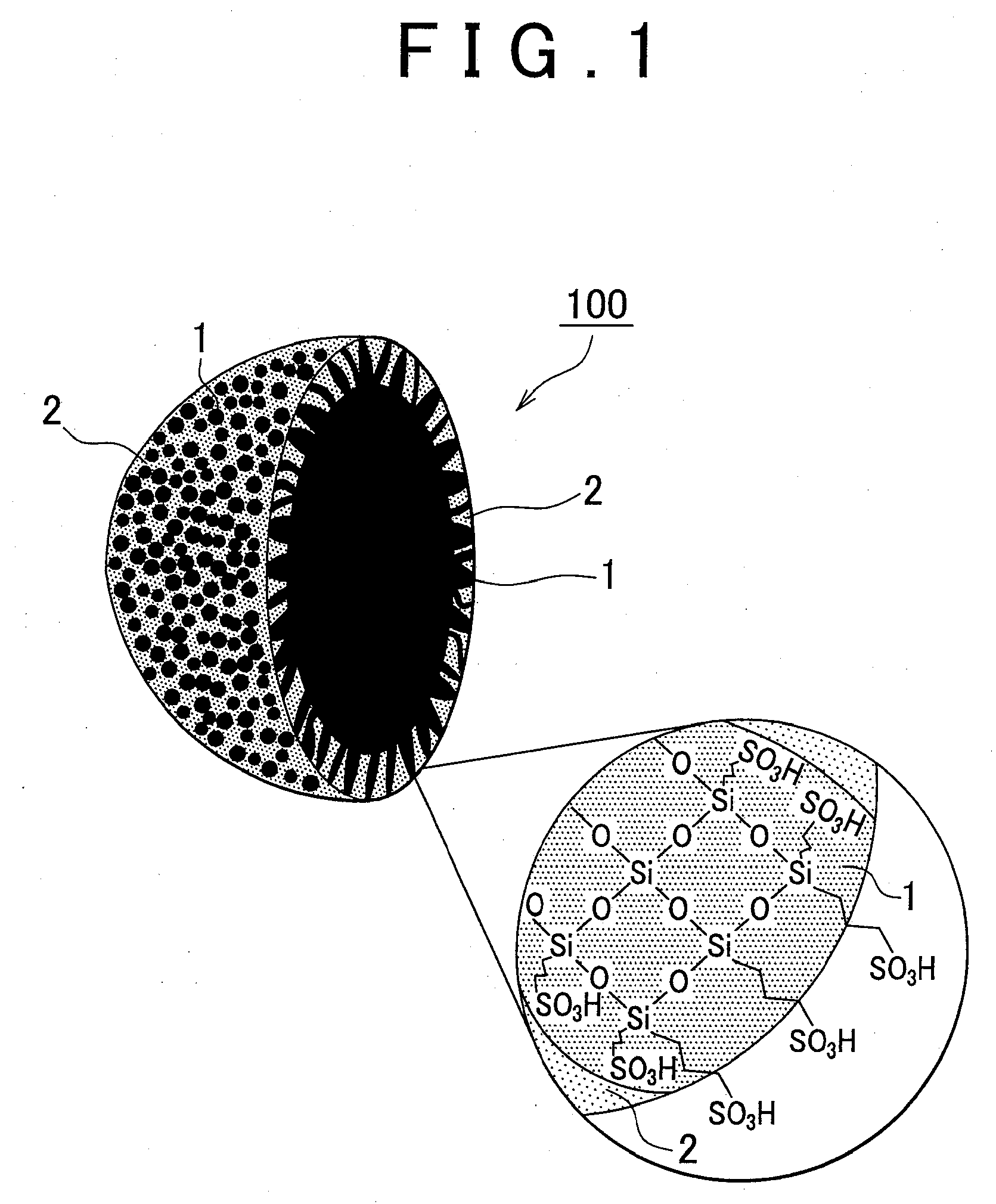
[0019]The proton conductive material according to the embodiment will be described below in greater detail with reference to the appended drawings. FIG. 1 is a cross-sectional view of a powdered proton conductive material illustrating schematically a proton conductive material of the embodiment. An enlarged drawing of a cross-section that illustrates schematically a structural formula of the electrolyte resin is shown in the circle in the lower right portion of the figure. Broken lines connecting silicon atoms and sulfonic acid groups (—SO3H) in the circle in the lower right portion of the figure represent alkyl chains. A proton conductive material 100 includes an electrolyte resin 1 and inorganic fine particles 2, and the hollow inorganic fine particles 2 are filled with the electrolyte resin 1. The inorganic fine particles 2 have a large number of through-holes, and the electrolyte resin 1 is exposed via the through-holes on the surface of the inorganic fine particles.

[0020]As ind...


PUM

PropertyMeasurementUnit
particle sizeaaaaaaaaaa
heat resistanceaaaaaaaaaa
sizeaaaaaaaaaa

Abstract

An electrolyte membrane for a fuel cell includes: a proton conductive material in which hollow inorganic fine particles having through-holes on the surface of the hollow inorganic fine particles, are filled with an electrolyte resin; and a non-proton conductive polymer.

Description

INCORPORATION BY REFERENCE[0001]The disclosure of Japanese Patent Application No. 2007-289844 filed on Nov. 7, 2007 including the specification drawings and abstract is incorporated herein by dereference in its entirety.BACKGROUND OF THE INVENTION[0002]1. Field of the Invention[0003]The present invention relates to an electrolyte membrane for a fuel cell.[0004]2. Description of the Related Art[0005]Fuel cells directly convert chemical energy into electric energy by supplying a fuel and an oxidizing agent to two electrodes that are electrically connected and electrochemically inducing oxidation of the fuel. By contrast with thermal power generation, fuel cells are not affected by the limitations of Carnot cycle and, therefore, demonstrate a high energy conversion efficiency. A fuel cell is usually configured by stacking a plurality of unit cells containing as a basic structure a membrane-electrode assembly (MEA) in which an electrolyte membrane is sandwiched between a pair of electro...

Claims


Application Information

Patent Timeline
Patent Type & Authority Applications(United States)
IPC IPC(8): H01M8/10
CPCH01M8/1023H01M8/1027H01M8/1037H01M8/1039Y02E60/521H01M8/1067H01M2008/1095H01M2300/0082H01M2300/0091H01M8/1051Y02E60/50
Inventor FUJINAMI, TATSUOMASE, TAKUYATAKAMI, MASAYOSHI
Owner NAT UNIV CORP SHIZUOKA UNIV
Why Eureka
Try Eureka