Devices, Methods, and Kits for a Biopsy Device

a biopsy device and kit technology, applied in medical science, surgery, vaccination/ovulation diagnostics, etc., can solve the problems of inability to aspirate a sample from a solid mass, inability to apply negative pressure, and inability to further damage the tissue, so as to facilitate the application of negative pressure, facilitate the echogenicity of the outer needle and facilitate the tissue collection element.

Inactive Publication Date: 2009-05-07
SHARP SURGICAL DEVICES
View PDF49 Cites 60 Cited by
  • Summary
  • Abstract
  • Description
  • Claims
  • Application Information

AI Technical Summary

Benefits of technology

[0008]Provided herein is a biopsy device comprising: an outer needle having a distal end and a proximal end connected to a drive mechanism; and a tissue collection element having a distal end and a proximal end, the tissue collection element formed from material having a first constrained configuration when positioned within the outer needle prior to deployment and a second unconstrained configuration when extended distally beyond the distal end of the outer needle, wherein the tissue collection element is translationally and rotationally moveable within the outer needle and distally beyond the distal end of the outer needle in response to actuation by the drive mechanism. The distal end of the tissue collection element can deviate from the central axis of the outer needle from 0 degrees to 180 degrees and rotates around the central axis of the outer needle from 0 degrees to about 360 degrees. The distal end of the tissue collection element can deviate from a central axis of the outer needle along an angle, radius, helical path, or contour. The distal end of the tissue collection element can comprise an opening, wherein the opening obtains a portion of tissue having a cross-sectional diameter greater than the cross-sectional diameter of the outer needle. The tissue collection element can be translated from within the outer needle to a target location. In some embodiments, the distal end of the tissue collection element is rotationally actuated to produce a rotational motion. Furthermore, the rotational motion can be a motion selected from the group consisting of continuous, intermittent, reciprocating, and combinations thereof. In some embodiments, the tissue collection element is adaptable to be moved manually. Alternatively, the tissue collection element is adaptable to be moved automatically or semi-automatically. Additionally, the outer needle of the biopsy device can be adaptable to or adapted and configured to be moved manually. Alternatively, the outer needle can be adaptable to be moved automatically or semi-automatically. In some embodiments of the device, the tissue collection element comprises stainless steel. In some embodiments of the tissue collection element, a portion of the tissue collection element comprises a shape memory alloy. Additionally, at least a portion of the tissue collection element can be coated with a non-friction coating, such as Teflon®, poly(tetrafluoroethylene), perfluoroalkoxy polymer resin, fluorinated ethylene-propylene, fluoropolymers, and combinations thereof. The distal end of the outer needle can be coated with a non-friction coating. In some embodiments, the distal end of the tissue collection element comprises a beveled

Problems solved by technology

These procedures often result in obtaining a small number of cells with each aspiration, cells which may or may not be diagnostic.
In addition, such procedures are often traumatic because of the multiple needle passes that it necessitates.
When injured, these enzymes are released, and may induce self digestion, and necrosis of the pancreas, and adjacent organs.
Aspirating a sample from a solid mass is difficult.
Even when tumor cells are captured, these are often fragmented, and separated from each other.
It is therefore almost impossib

Method used


Image

  • Devices, Methods, and Kits for a Biopsy Device
  • Devices, Methods, and Kits for a Biopsy Device
  • Devices, Methods, and Kits for a Biopsy Device

Examples


Embodiment Construction

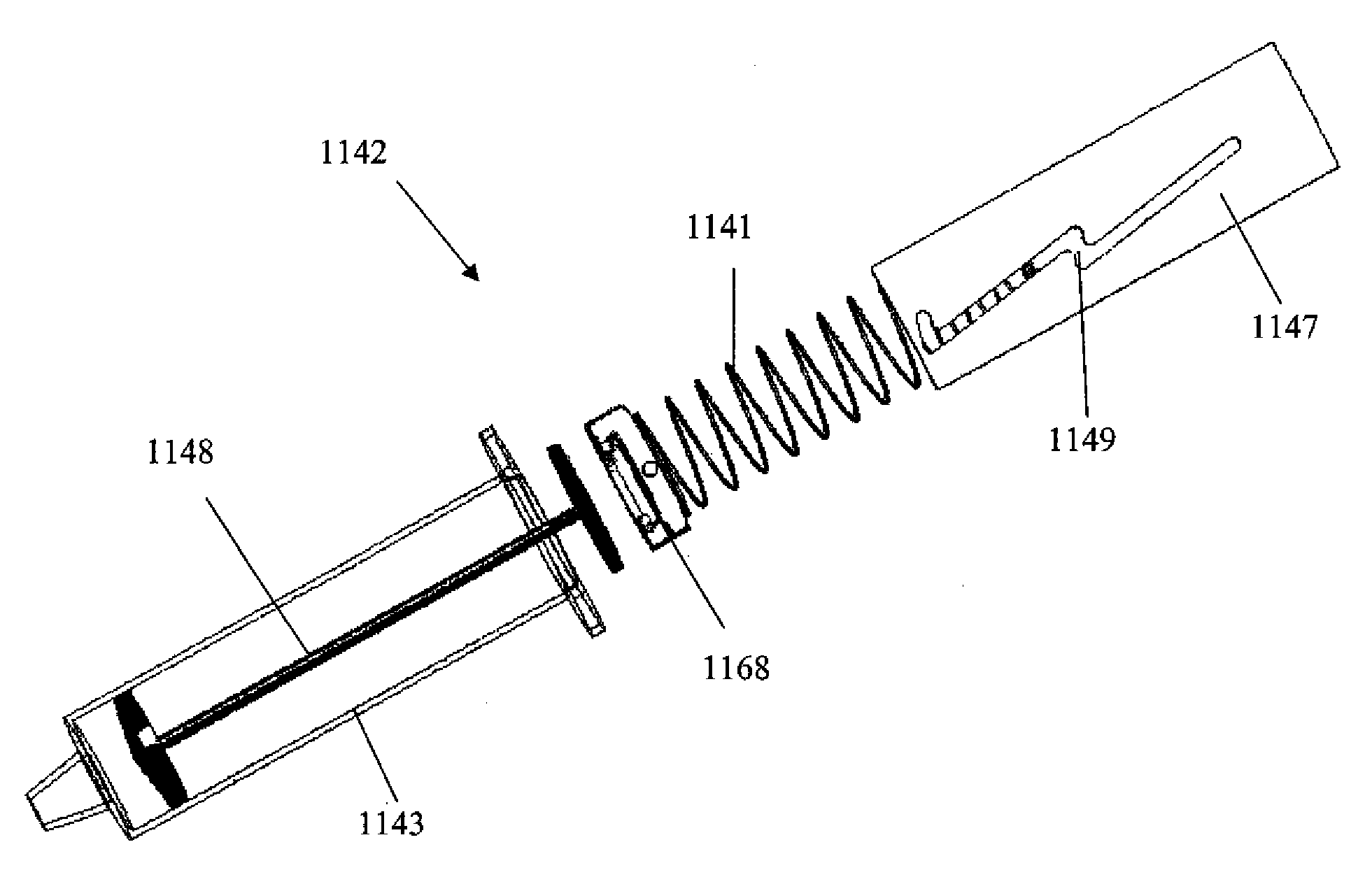
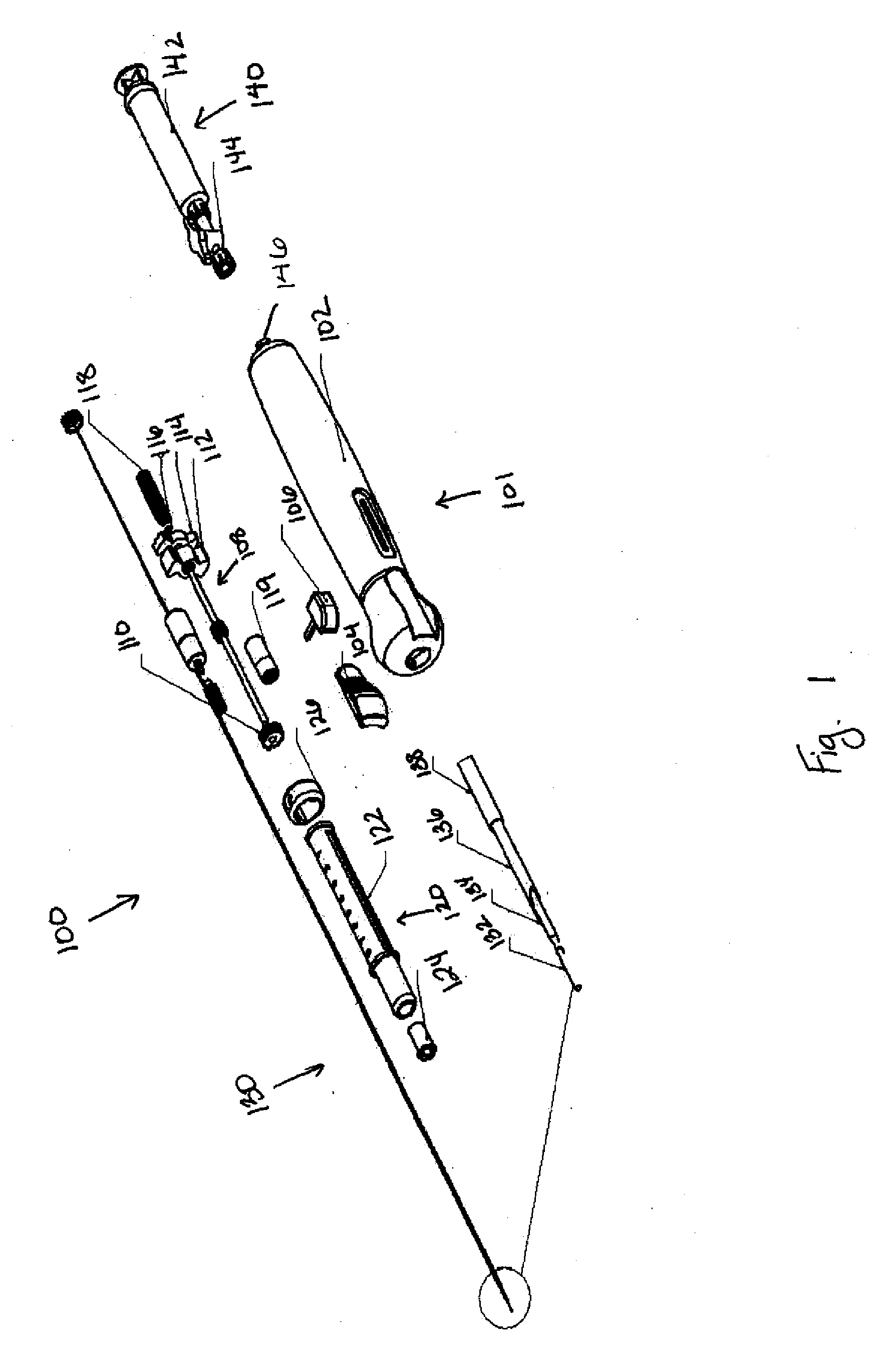
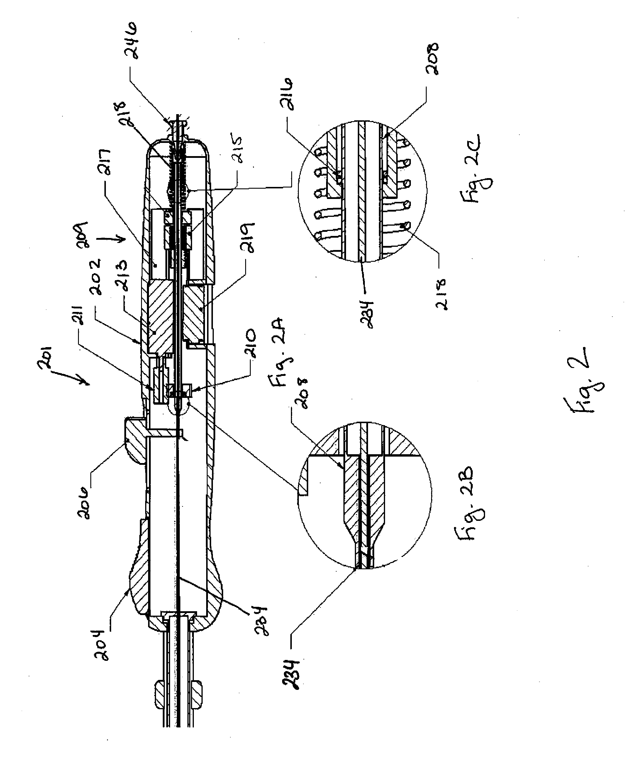
[0040]The biopsy devices described herein can be designed to automate the procedure for the diagnosis of suspect areas of tissue. The device can be used with tumors and cysts, or any other suitable soft tissue from which a sample can be obtained. Various embodiments of the device are provided herein. In one embodiment, the device described herein can comprise an outer needle having a distal end, or end closer to the body, and a proximal end, or end closer to the exterior of the body, connected to a drive mechanism and a tissue collection element having a distal end and a proximal end. The distal end of the tissue collection element can be formed from a material having a first constrained configuration when positioned within the outer needle prior to deployment and a second unconstrained configuration when extended distally beyond the distal end of the outer needle, wherein the tissue collection element is translationally and rotationally moveable within the outer needle and distally...


PUM


Abstract

Provided herein are biopsy devices each comprised of a tissue collection element having a distal end and a proximal end connected to a drive mechanism. In one embodiment, the tissue collection element can be formed from a material having a first constrained configuration when positioned within the outer needle prior to deployment and a second unconstrained configuration when extended distally beyond the distal end of the outer needle. In another embodiment, the tissue collection element can be formed from a material having a first constrained configuration when a stylet is inserted into the tissue collection element and a second unconstrained configuration when the stylet is retracted from within the tissue collection element. In a third embodiment, the tissue collection element comprises a helical cutting edge along at least a portion of the length of the tissue collection element, wherein the helical cutting edge is adaptable to cut a portion of tissue from the target location. The tissue collection element is translationally and rotationally moveable within a target location in response to actuation by the drive mechanism, thereby collecting tissue. The biopsy devices provided herein can further comprise provisions for echogenecity, a non-friction coating at the tip, and means for providing aspiration. Further provided herein are methods for using the devices described and a kit.

Description

CROSS-REFERENCE[0001]This application claims the benefit of U.S. Provisional Application No. 60 / 984,997, filed Nov. 2, 2007, which application is incorporated herein by reference.BACKGROUND OF THE INVENTION[0002]Fine needle aspiration (FNA) has been a well-accepted method for obtaining tissue samples for pathologic or histologic analysis in diagnosing tumors of the pancreas and other soft tissue organs. Endoscopic ultrasound (EUS) and EUS-guided fine needle aspiration (EUS-FNA) have become important tools in the evaluation of pancreatic masses.[0003]Conventional surgical techniques for obtaining tissue samples accessible only through a flexible ultrasound-endoscope using a fine needle generally require numerous needle sticks. These procedures often result in obtaining a small number of cells with each aspiration, cells which may or may not be diagnostic. In addition, such procedures are often traumatic because of the multiple needle passes that it necessitates. This is especially tr...

Claims


Application Information

Patent Timeline
IPC IPC(8): A61B10/02
CPCA61B10/0266A61B2017/00685A61B2017/00331A61B2010/0208
Inventor VAN DAM, JACQUESCYBULSKI, JAMES S.GURUKULA, VENKATA
Owner SHARP SURGICAL DEVICES
Why Eureka
Try Eureka