Fuel injector designed to minimize mechanical stress on fuel pressure sensor installed therein

a technology of fuel pressure sensor and fuel injector, which is applied in the direction of electrical control, process and machine control, etc., can solve the problems of internal stress increasing, reducing the accuracy of determining such a pressure change, and not ensuring the desired accuracy in determining fuel pressure change, etc., to ensure the accuracy of measuring a change in fuel pressur

Active Publication Date: 2009-05-07
DENSO CORP +1
View PDF6 Cites 7 Cited by
  • Summary
  • Abstract
  • Description
  • Claims
  • Application Information

AI Technical Summary

Benefits of technology

[0013]It is another object of the invention to provide a fuel injector for an internal combustion engine which may be employed in automotive diesel common rail injection system and which is so designed to minimize the internal stress of an injector body on a fuel pressure sensor installed in the injector body to ensure the accuracy in measuring the pressure of fuel in the fuel injector.
[0015]Specifically, the fuel pressure sensor is disposed away from a portion of the injector body where the internal stress will increase when the fuel injector is in use, that is, between a portion of the injector body retained in the cylinder head of the engine and the second portion on which the mechanical pressure is exerted. This keeps the fuel pressure sensor free from the internal stress of the injector body, thus ensuring the accuracy in measuring a change in pressure of the fuel arising from spraying of the fuel from the fuel injector.

Problems solved by technology

For instance, in the case where a change in pressure of the fuel arising from the spraying of the fuel from the fuel injector (which will also be referred to as a fuel pressure change below) is measured using a pressure sensor installed directly in a common rail (i.e., a fuel accumulator), it will be somewhat absorbed within the common rail, thus resulting in a decrease in accuracy in determining such a pressure change.
The use of the pressure sensor installed in the joint between the common rail and the high-pressure pipe, therefore, does not ensure the desired accuracy in determining the fuel pressure change.
Such installation, however, has been found to pose the problems, as discussed below.
The exertion of the pressure F1 or F2 from the high-pressure pipe HP will cause internal stress to increase, which acts on a fuel pressure sensor 50x installed in the fuel injector, thus resulting in a decrease in accuracy in measuring the pressure of fuel.

Method used


Image

  • Fuel injector designed to minimize mechanical stress on fuel pressure sensor installed therein
  • Fuel injector designed to minimize mechanical stress on fuel pressure sensor installed therein
  • Fuel injector designed to minimize mechanical stress on fuel pressure sensor installed therein

Examples


Embodiment Construction

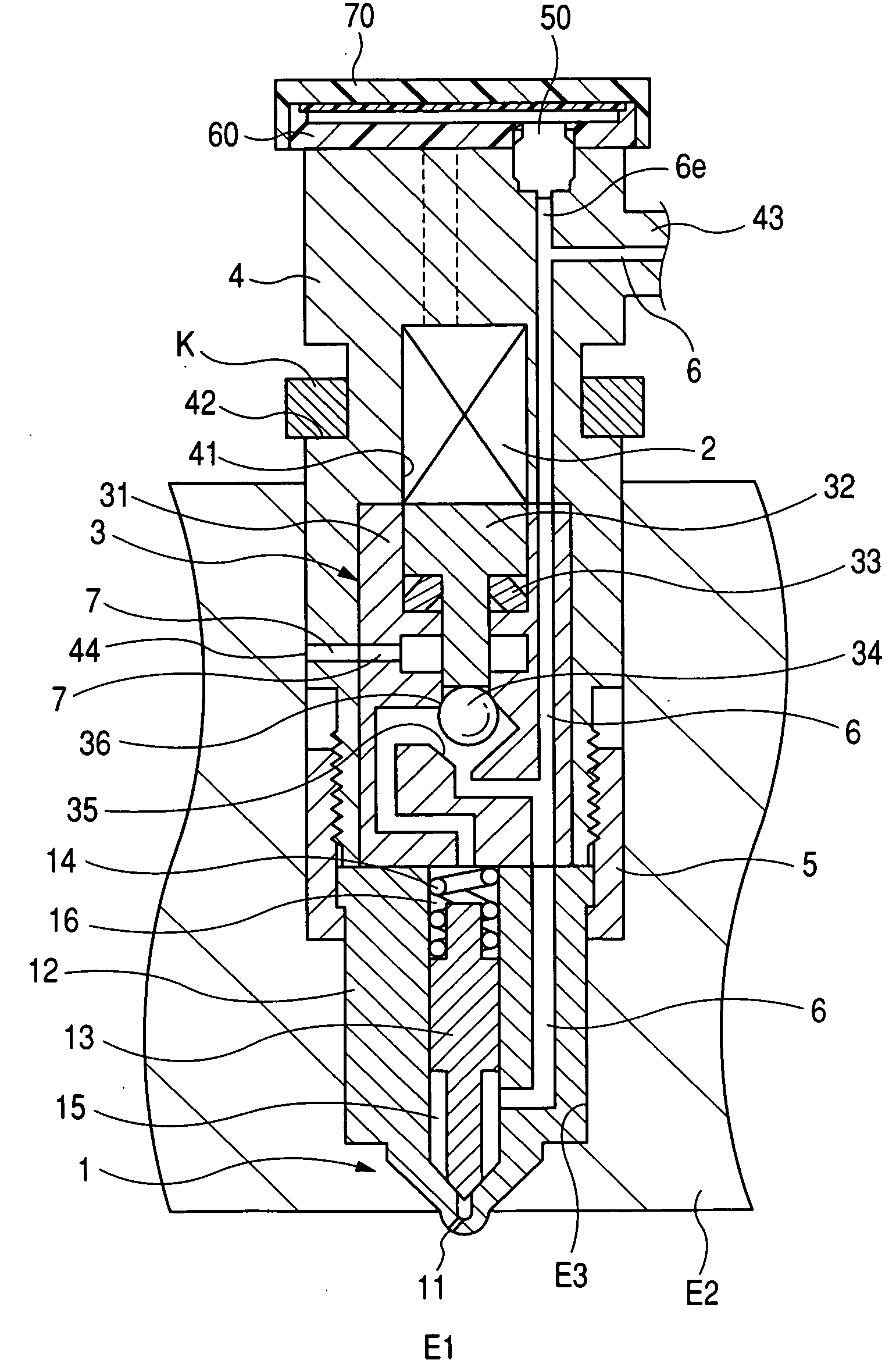
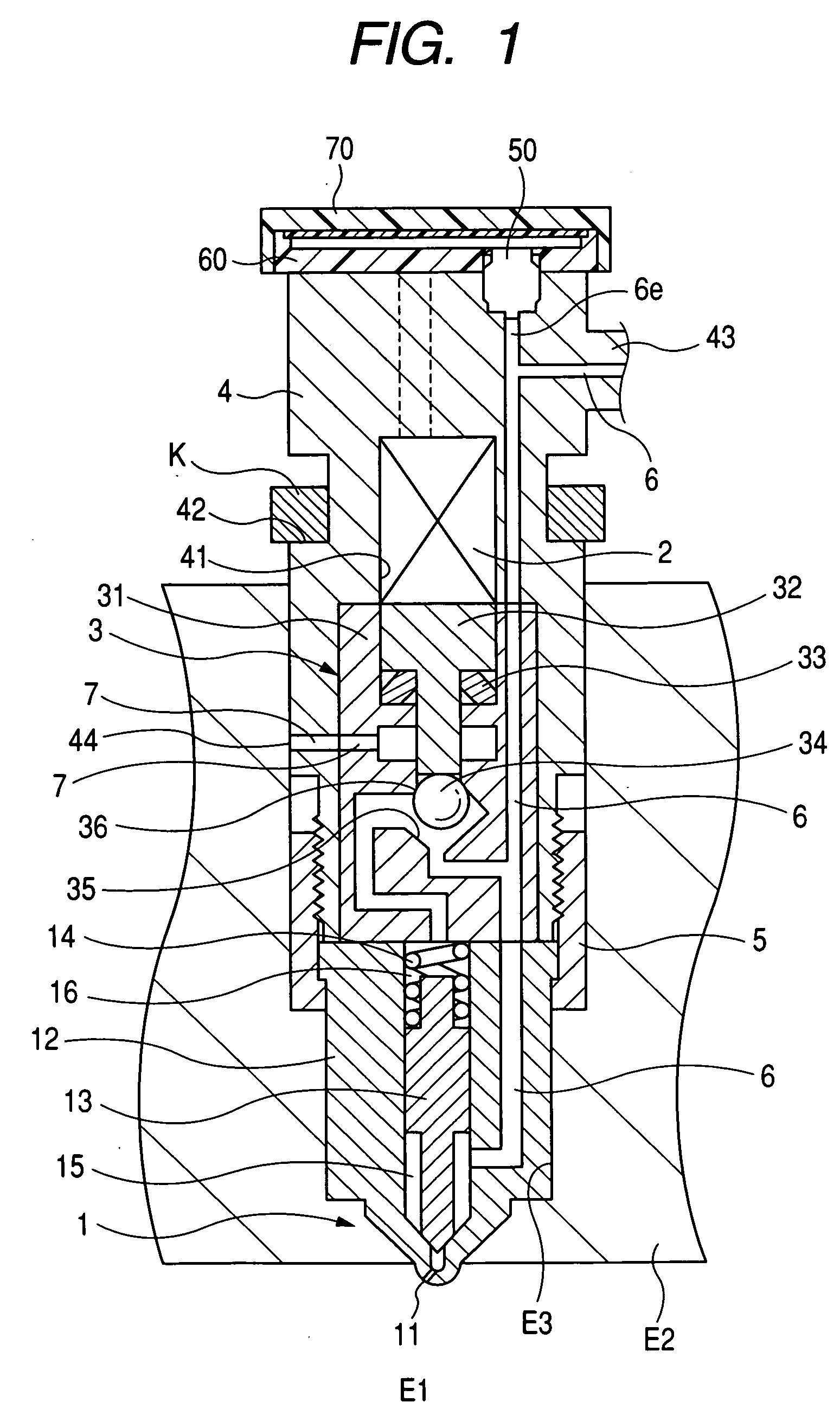
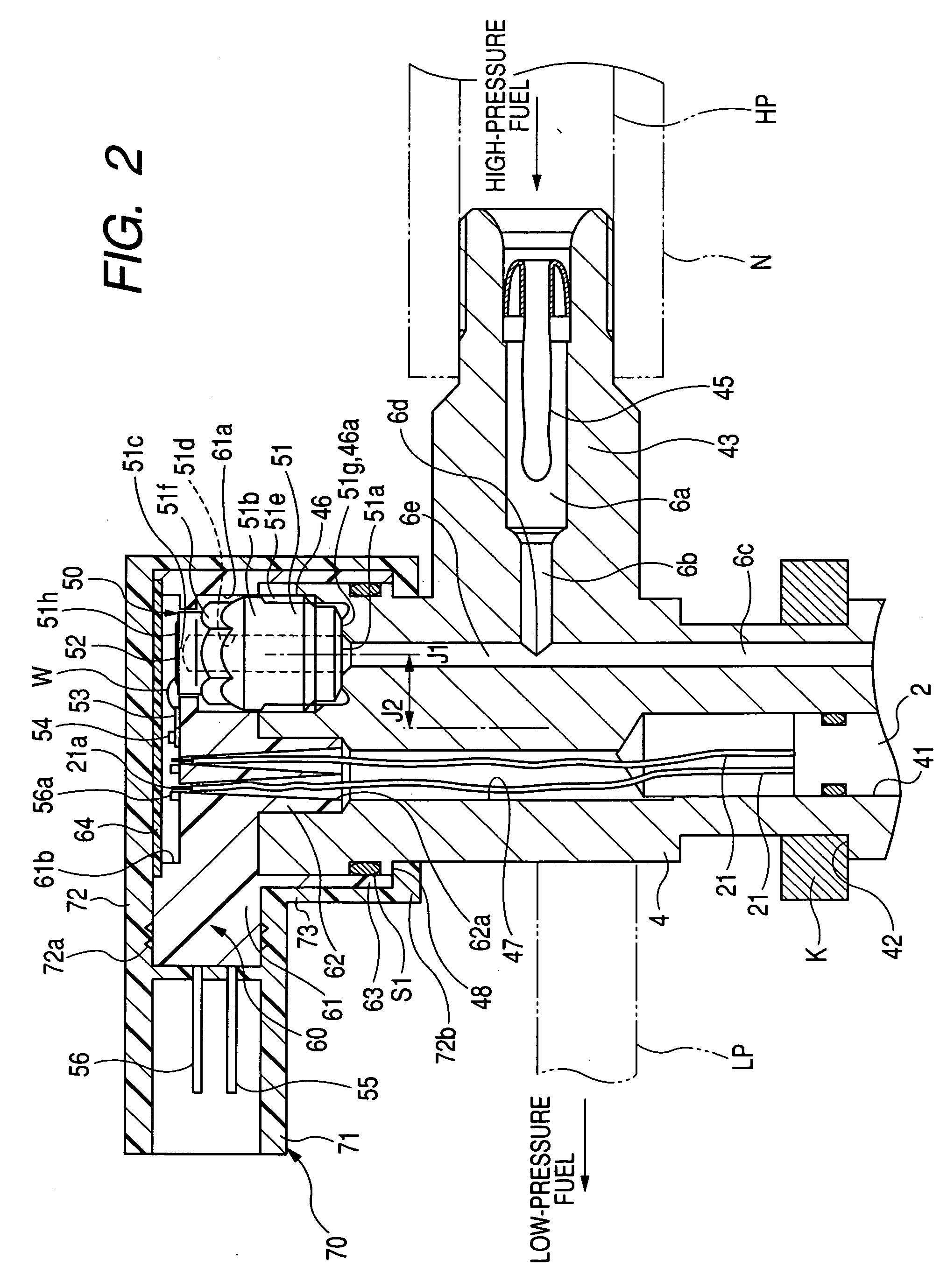
[0027]Referring to the drawings, wherein like reference numbers refer to like parts in several views, particularly to FIGS. 1 and 2, there is shown a fuel injector according to the first embodiment of the invention which will be referred to herein as being used in, for example, automotive common rail fuel injection Systems for diesel engines.

[0028]The fuel injector works to inject the fuel, as stored in a common rail (not shown) at controlled high pressures, into a combustion chamber E1 in a cylinder of an internal combustion diesel engine. The fuel injector is equipped with a nozzle 1 from which the fuel is sprayed, a piezoelectric actuator 2 which serves as an open / close mechanism and expands when electrically charged and contracts when discharged, and a back-pressure control mechanism 3 which is operated by the piezoelectric actuator 2 to control the back pressure acting on the nozzle 1.

[0029]The nozzle 1 is made up of a nozzle body 12 in which a spray hole(s) 11 is formed, a nee...


PUM


Abstract

A fuel injector for an internal combustion engine is provided. The fuel injector is to be installed in a cylinder head of the engine and has a fuel pressure sensor working to measure the pressure of fuel within a injector body. The fuel pressure sensor is installed in a portion of the injector body which is to be located away from the cylinder head of the engine across a portion of the injector body on which a mechanical pressure is exerted by an external member such as a fuel supply pipe or a fuel drain pipe, thereby keeping the fuel pressure sensor free from internal stress, as arising from the mechanical pressure exerted on the injector body, to ensure the accuracy in measuring the pressure of the fuel.

Description

CROSS REFERENCE TO RELATED DOCUMENT[0001]The present application claims the benefit of Japanese Patent Application No. 2007-289077 filed on Nov. 6, 2007, the disclosure of which is incorporated herein by reference.BACKGROUND OF THE INVENTION[0002]1. Technical Field of the Invention[0003]The present invention relates generally to a fuel injector to be mounted in an internal combustion engine to spray fuel thereinto, and more particularly to such a fuel injector which has installed therein a fuel pressure sensor working to measure a change in pressure of the fuel arising from the spraying of the fuel into the engine and which is designed to minimize mechanical stress on the fuel pressure sensor.[0004]2. Background Art[0005]In order to ensure the accuracy in controlling output torque of internal combustion engines and the quantity of exhaust emissions therefrom, it is essential to control a fuel injection mode such as the quantity of fuel to be sprayed from a fuel injector or the injec...

Claims


Application Information

Patent Timeline
Patent Type & Authority Applications(United States)
IPC IPC(8): F02D41/00
CPCF02M47/027F02M57/005F02M2200/24F02M63/0026F02M61/14
Inventor KONDO, JUNTAGUCHI, TOORUARIKAWA, FUMIAKI
Owner DENSO CORP
Why Eureka
Try Eureka