
Deployable aircraft/spacecraft propulsion system and methods

Inactive Publication Date: 2009-05-14
KOHN ARYEH YAAKOV
View PDF11 Cites 5 Cited by
  • Summary
  • Abstract
  • Description
  • Claims
  • Application Information

AI Technical Summary

Benefits of technology

[0014]There is additionally provided a method of operating a propulsion system for a combined aircraft/spacecraft comprising the steps of: reducing the altitude of the combined aircraft/spacecraft to an upper altitude range; and stowing a rocket engine from behind the jet engine, outside of a common engine housin

Problems solved by technology

Because atmospheric propulsion systems utilize atmospheric oxygen, most aircraft utilizing such propulsion systems are limited to operation up to altitudes ranging from approximately 45,000 to 65,000 feet or less, depending on the specific type of system and respective system operating conditions.
However, since rocket propulsion systems must have all of their fuel and oxidizer carried on board, in addition to the necessary rocket engine components, there is a serious consideration of increased flight weight when compared to typical aircraft propulsion systems.
Disposability of subsystems or a disposable overall system typically contributes to increased cost.
Therefore, rocket propulsion systems are usually limited to non-atmospheric flight, meaning flight at very high altitude or in space.
When separate jet and rocket engines are employed in a combined aircraft / spacecraft, a distinct disadvantage is that the respective engines occupy extra space when, for example, they are mounted on the wings or externally to the fuselage of an aircraft / spacecraft.
In addition to the consideration of extra space occupied by respectively externally mounted engines, another more serious disadvantage is that of additional drag caused by the rocket engine, typically not operated in lower altitudes, upon the aircraft / spacecraft when it is flown in an atmosphere.
A combined jet and rocket engine configuration, while offering an advantage of space and drag savings, due to the functioning of both the jet and rocket engine within the same fairing, has an apparent disadvantage in that such a configuration requires a special engine design, undoubtedly leading to unconventional manufacturing considerations.

Method used


Image

  • Deployable aircraft/spacecraft propulsion system and methods
  • Deployable aircraft/spacecraft propulsion system and methods
  • Deployable aircraft/spacecraft propulsion system and methods

Examples


Embodiment Construction

[0020]The present invention is a deployable propulsion system and methods that can be used for a combined aircraft / spacecraft.

[0021]The principles and operation of a deployable propulsion system used for a combined aircraft / spacecraft according to the present invention may be better understood with reference to the drawings and the accompanying description.

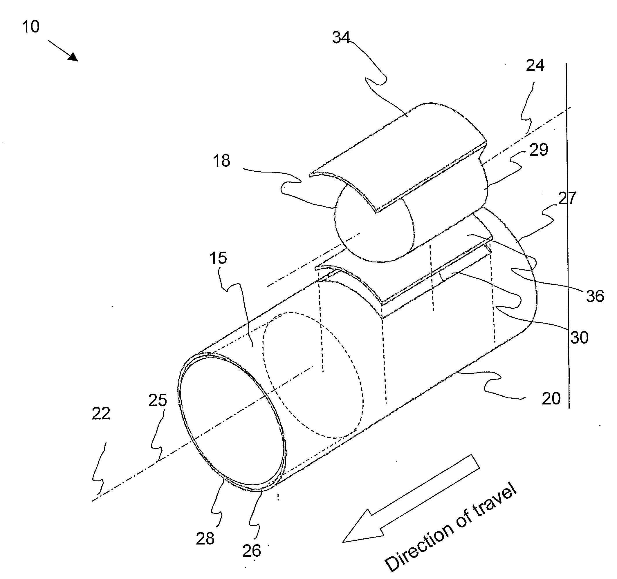
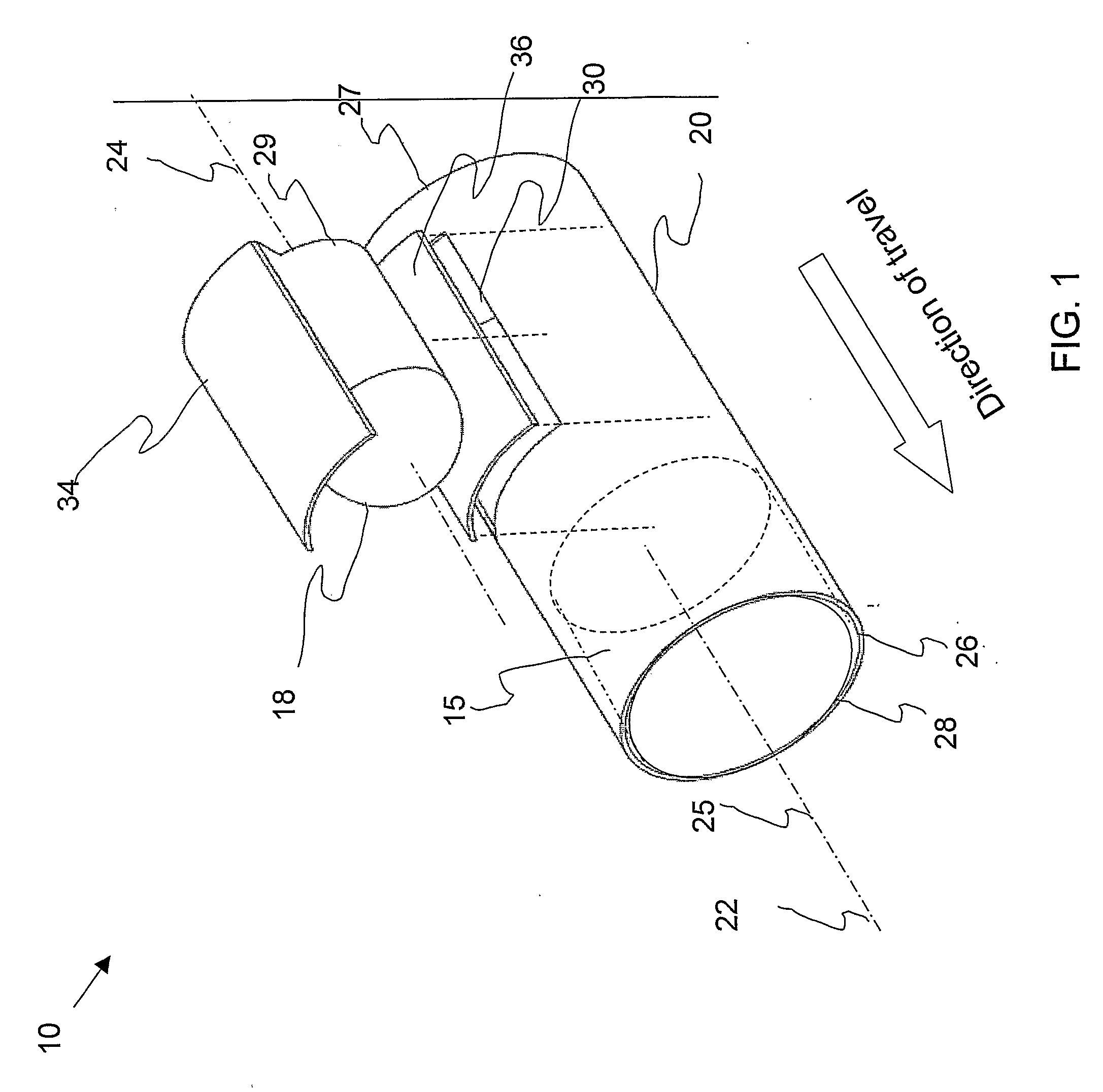
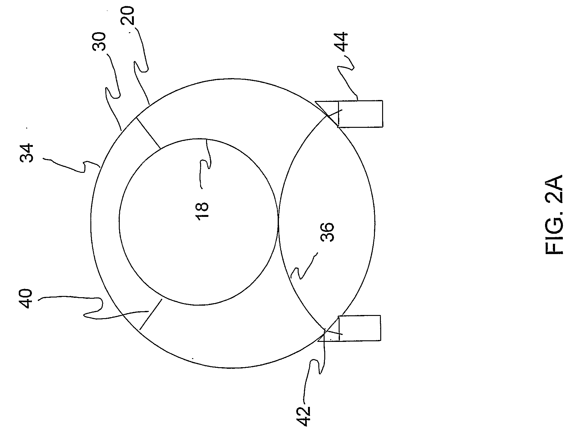
[0022]Referring now to the drawings, FIG. 1 is a schematic illustration of a propulsion system 10 for a combined aircraft / spacecraft (not shown in the figure) including a jet engine 15, a rocket engine 18, and a common engine housing 20, in accordance with an embodiment of the current invention. Jet engine 15 has an approximate cylindrical type shape and a jet engine axis 22 as indicated and rocket engine 18 has an approximate cylindrical type shape and a rocket engine axis 24 as indicated. Common engine housing 20, which typically has an elongated cylindrical-type or rectangular parallelepiped type-shape, has a housing axis 25 as...


PUM


Abstract

A propulsion system for a combined aircraft / spacecraft including: a jet engine having a longitudinal axis defined in a direction from a front end at an air intake to a rear end at a jet exhaust: a front end at an air intake to a rear end at the jet exhaust; a rocket engine having a longitudinal axis defined normal to a rear end at a rocket exhaust; a common engine housing having an elongated shape and wherein the jet engine and the rocket engine are configured substantially coaxially and with respective rear ends facing the same direction when the rocket engine is operated.

Description

FIELD AND BACKGROUND OF THE INVENTION[0001]The present invention relates to propulsion in aeronautics and astronautics and, in particular, it concerns a deployable propulsion system and methods that can be used for a combined aircraft / spacecraft.[0002]It is known that aircraft employ atmospheric propulsion systems that typically combine liquid fuel that is burnt with atmospheric oxygen to provide power and / or thrust for flight. Propulsion systems which operate in this way include: internal combustion engines (typically powering propellers); and an array of jet engines such as turboprops, fan gas turbines, ram jets and scram jets. In the specification and in the claims that follow, “jet engine” means any of the aforementioned or other variations of gas turbine engines. A reference for various jet and rocket engines, including other technological and general considerations, may be found in “The Standard Handbook for Aeronautical and Astronautical Engineers”, by Davies (2002), whose di...

Claims


Application Information

Patent Timeline
IPC IPC(8): F02K9/00
CPCF02K9/78F02K7/18
Inventor KOHN, ARYEH YAAKOV
Owner KOHN ARYEH YAAKOV
Learn More