Precision roll turning lathe

Active Publication Date: 2009-05-14
TOSHIBA MASCH CO LTD
View PDF7 Cites 6 Cited by
  • Summary
  • Abstract
  • Description
  • Claims
  • Application Information

AI Technical Summary

Benefits of technology

[0020]The precision roll turning lathe of the present invention can perform machining of fine grooves at a dramatically higher speed as compared to conventional roll turning lathes, thus significantly shortening time taken for machining one groove. Further, roll machining, which has a heavy workload of ultraprecision machining, ca

Problems solved by technology

Ultraprecision machining of a roll mold by means of such a roll turning lathe involves the problem that it takes a long time to complete machining of one roll.
When an air slide apparatus is used in precision machining of a roll, how to supply air and electric power to an ai

Method used


Image

  • Precision roll turning lathe
  • Precision roll turning lathe
  • Precision roll turning lathe

Examples


first embodiment

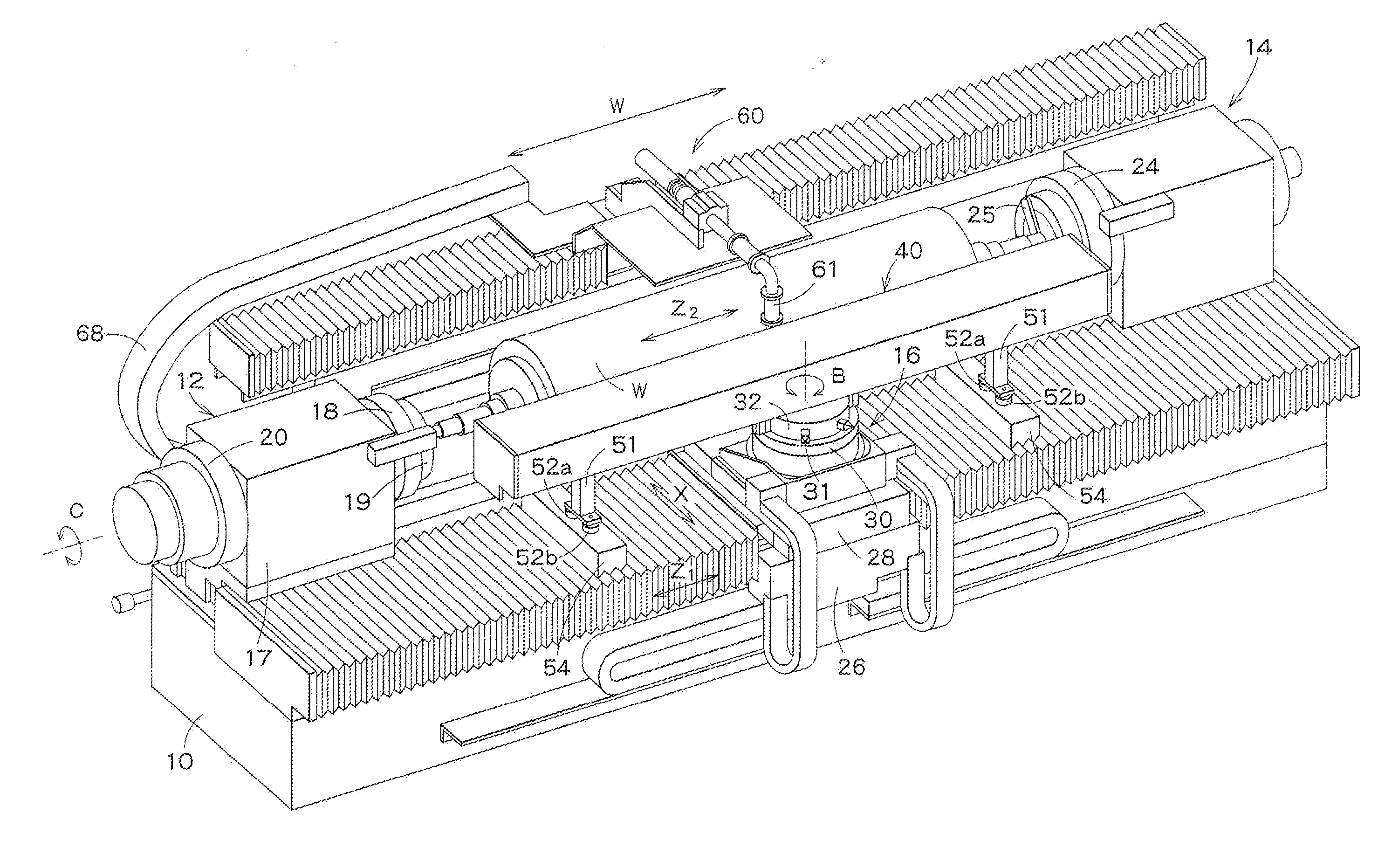
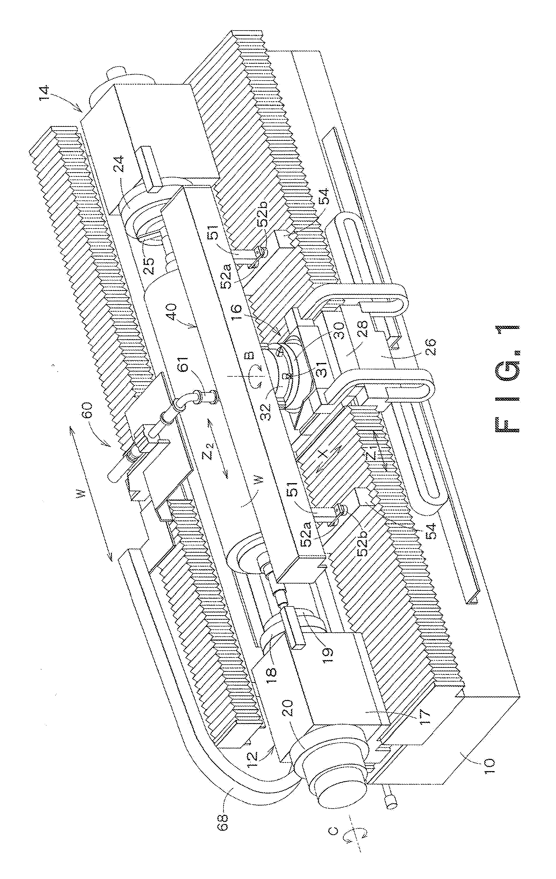
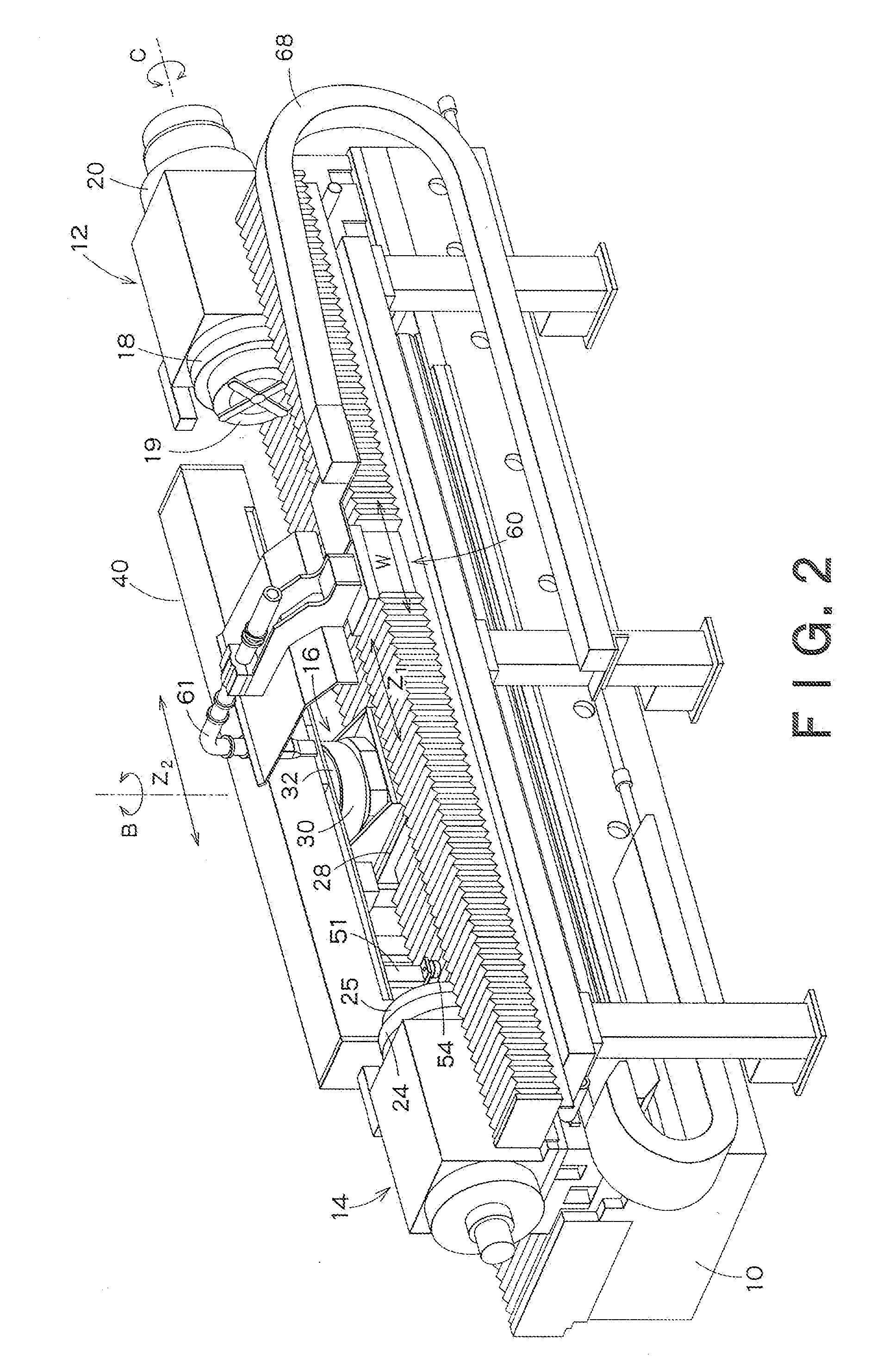
[0030]FIG. 1 is a perspective front view of a precision roll turning lathe according to a first embodiment of the present invention, and FIG. 2 is a perspective rear view of the precision roll turning lathe without a roll set in it.

[0031]In FIGS. 1 and 2, reference numeral 10 denotes a bed. On the bed 10 are mounted a headstock 12, a tail stock 14 and a carriage 16. A roll W as a workpiece is rotatably supported by the headstock 12 and the tail stock 14.

[0032]The headstock 12 is disposed on one longitudinal end of the bed 10. The headstock 12 includes a body 17, a main spindle 18, a chuck 19 secured to the front end of the main spindle 18, and a servo motor 20 for driving the main spindle 18. The main spindle 18 is supported by a not-shown hydrostatic oil bearing provided within the body 17. The chuck 19 holds a spindle of the roll W and transmits the rotation of the main spindle 18 to the roll W.

[0033]In the headstock 12, the servo motor 20 for driving the main spindle 18 is a buil...

second embodiment

[0068]A precision roll turning lathe according to a second embodiment of the present invention will now be described with reference to FIG. 7.

[0069]The roll turning lathe of this embodiment is characterized by the provision of the cutting chip suction apparatus 60 shown in FIG. 7. As shown in FIG. 7, the cutting chip suction apparatus 60 includes a moving table 61 and a support arm 62. The moving table 61 moves on the bed 10 in a direction parallel to the moving direction of the air slider 41. A ball screw is employed as a drive mechanism for the moving table 61 with a W axis as its control axis.

[0070]The support arm 62 is fixed on the moving table 61, and the support arm 62 extends toward the roll W. A suction pipe 63 is supported by the support arm 62. A joint 64 is mounted to the downwardly-bent end of the suction pipe 63, and a suction nozzle 65 is connected via the joint 64 to the suction pipe 63. The front end of the suction nozzle 65 is to be positioned close to the diamond t...


PUM

PropertyMeasurementUnit
Forceaaaaaaaaaa
Angleaaaaaaaaaa
Electric potential / voltageaaaaaaaaaa

Abstract

There is provided a precision roll turning lathe which can perform machining of fine grooves at a dramatically higher speed as compared to conventional roll turning lathes, thus significantly shortening time taken for machining one groove. The precision roll turning lathe includes: a bed; a headstock, mounted on the bed, having a main spindle for rotating a roll as a workpiece while holding one end of the roll by means of a chuck; a tail stock, mounted on the bed and disposed opposite the headstock, for rotatably supporting the other end of the roll; a carriage including a saddle mounted on the bed movably in the longitudinal direction of the roll, and a table mounted on the saddle movably in a direction perpendicular to the longitudinal direction of the roll; and an air slide apparatus, mounted on the table, including a guide rail extending parallel to the roll in the longitudinal direction, an air slider having a diamond tool, capable of traveling in a floating state on the guide rail, and a linear motor for driving the air slider.

Description

BACKGROUND OF THE INVENTION[0001]1. Field of the Invention[0002]The present invention relates to a precision roll turning lathe, and more particularly to a precision roll turning lathe for use in machining of a roll mold for extrusion molding of an optical product, such as a lens sheet.[0003]2. Background Art[0004]A roll turning lathe is among machine tools for machining rolls. A roll turning lathe is a lathe in which a tool post, having e.g. diamond tools attached thereto, is mounted in a carriage, and is basically used for machining circumferential grooves in a roll by rotating the roll with a headstock and feeding the carriage in the lateral direction (X-axis direction) of the roll. When machining axial grooves in a roll, the carriage is fed in the longitudinal direction (Z-axis direction) of the roll while indexing the roll with the headstock (C axis), thereby producing the axial grooves.[0005]The recent advancement of machine control technology has realized ultraprecision machi...

Claims


Application Information

Patent Timeline
IPC IPC(8): B23B5/08B23B11/00B23B21/00B23Q1/28
CPCB23B5/08B23B2220/12B23C2226/31Y10T82/2535B23Q1/38Y10T82/2533Y10T82/2541B23D11/00B27C7/00B23B25/00B23B11/00
Inventor AKIYAMA, TAKANOBU
Owner TOSHIBA MASCH CO LTD
Why Eureka
Try Eureka