
Removal of carbon dioxide from air

a technology of carbon dioxide and air, applied in the direction of sulfur compounds, hydrogen sulfides, separation processes, etc., can solve the problems of large-scale hydrocarbon-fueled power plants that are not fully protected from exhausting cosub>2 /sub>into the atmosphere, the number of small-scale, widely-distributed emitters that are impractical to mitigate at the source, and the need to curtail cosub>2 /sub>emissions from all sources

Active Publication Date: 2009-05-14
CARBON SINK
View PDF99 Cites 135 Cited by
  • Summary
  • Abstract
  • Description
  • Claims
  • Application Information

AI Technical Summary

Benefits of technology

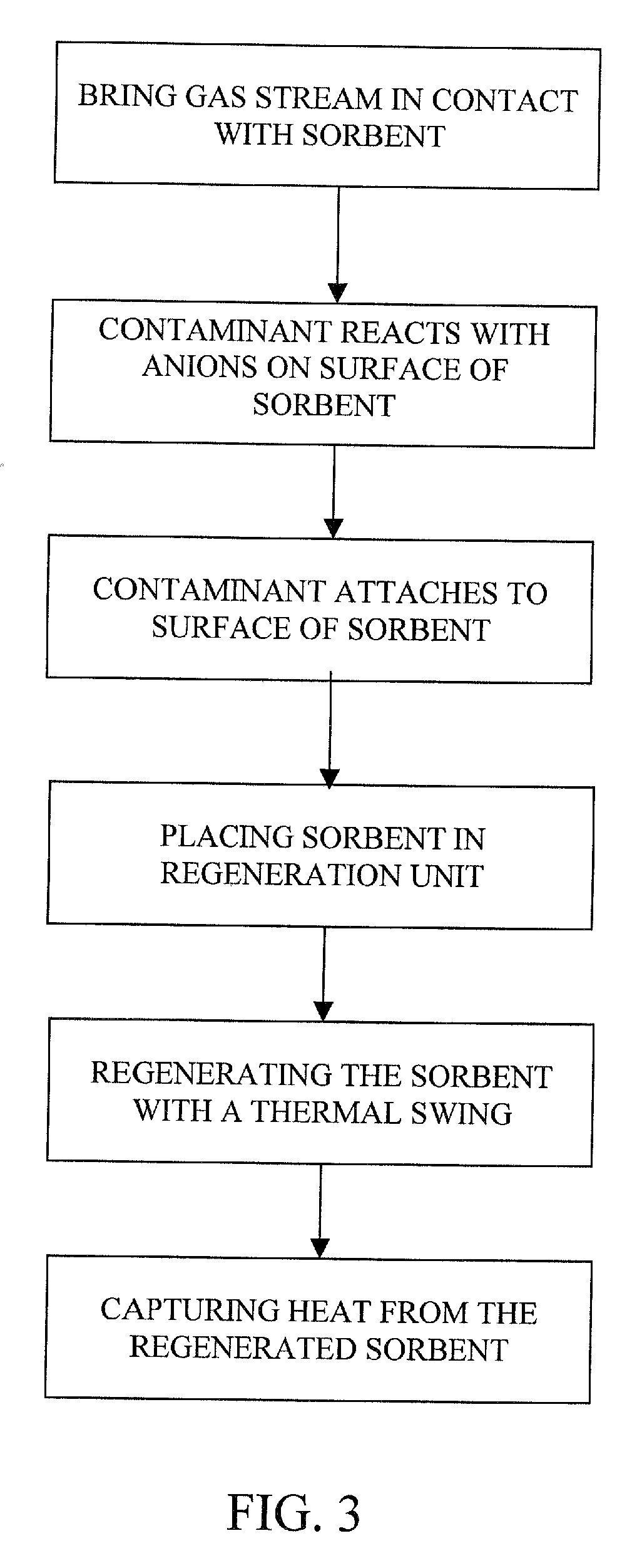
[0009]To conserve energy, the present invention may employ a heat exchanger using water as a refrigerant, wherein the water is evaporated in an evacuated space to draw heat from the regenerated sorbent and the water is then condensed on the sorbent loaded with the contaminant. The use of other fluids as refrigerants is also contemplated. Alternatively, the refrigerant may be isolated from the sorbent so as not to interfere with the thermal function of the sorbent.

Problems solved by technology

Of the various sources of the CO2 emissions, there are a vast number of small, widely distributed emitters that are impractical to mitigate at the source.
Additionally, large scale emitters such as hydrocarbon-fueled power plants are not fully protected from exhausting CO2 into the atmosphere.
However, as greenhouse gas concerns mount, CO2 emissions from all sources will have to be curtailed.
None of these references, however, provides a particularly efficient process for the removal of CO2, primarily due to the amount of energy expended in CO2 recovery and sorbent regeneration.

Method used


Image

  • Removal of carbon dioxide from air
  • Removal of carbon dioxide from air
  • Removal of carbon dioxide from air

Examples


Embodiment Construction

[0024]The present invention provides a method and apparatus for the extraction of a contaminant from a gas stream. The present invention is discussed in reference to a method and apparatus for capturing CO2 from ambient air, but the technology is also applicable to exhaust air or other gas streams and may be used to capture hydrogen sulfide, ammonia, or other common contaminants from such gas streams.

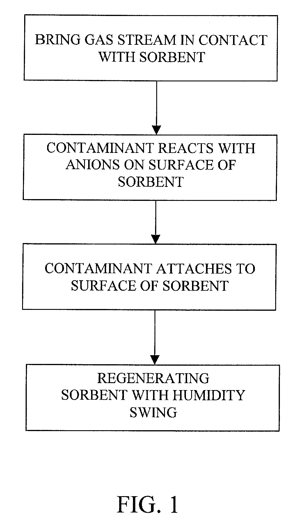
[0025]In co-pending patent application Ser. No. PCT / US07 / 84880, assigned to a common assignee and incorporated by reference herein, we discuss a CO2 capture process that utilizes a humidity swing to regenerate a sorbent, releasing a mixture of CO2 and water vapor. The water vapor may be removed from the mixture by compression or cooling, either of which will cause the water vapor to condense and precipitate out of the mixture.

[0026]A first aspect of the present invention provides an improved substrate that can hold cations embedded into its surface, thereby facilitating the capture and ...


PUM

PropertyMeasurementUnit
Temperatureaaaaaaaaaa
Electric potential / voltageaaaaaaaaaa
Heataaaaaaaaaa

Abstract

The present invention provides a method and apparatus for removing a contaminant, such as carbon dioxide, from a gas stream, such as ambient air. The contaminant is removed from the gas stream by a sorbent which may be regenerated using a humidity swing, a thermal swing, or a combination thereof. The sorbent may comprise a substrate having embedded positive ions and individually mobile negative ions wherein the positive ions are sufficiently spaced to prevent interactions between the negative ions. Where a thermal swing is used, heat may be conserved by employing a heat exchanger to transfer heat from the regenerated sorbent to an amount of sorbent that is loaded with the contaminant prior to regeneration.

Description

CROSS REFERENCE TO RELATED APPLICATIONS[0001]The present application claims priority from U.S. Provisional Application Ser. No. 60 / 985,586, filed Nov. 5, 2007; the contents of which are incorporated herein by reference.FIELD OF THE INVENTION[0002]The present invention relates to removal of selected gases from air. The invention has particular utility for the extraction of carbon dioxide (CO2) from air and will be described in connection with such utilities, although other utilities are contemplated.BACKGROUND OF THE INVENTION[0003]There is compelling evidence to suggest that there is a strong correlation between the sharply increasing levels of atmospheric CO2 with a commensurate increase in global surface temperatures. This effect is commonly known as Global Warming. Of the various sources of the CO2 emissions, there are a vast number of small, widely distributed emitters that are impractical to mitigate at the source. Additionally, large scale emitters such as hydrocarbon-fueled p...

Claims


Application Information

Patent Timeline
IPC IPC(8): B01D53/04B03C3/00B01D53/047C01B32/50
CPCB01D53/0462B01D53/62B01D2253/10B01D2253/108B01D2253/206Y02C10/08B01D2257/406B01D2257/504Y02C10/04Y02C10/06B01D2257/304Y02C20/40
Inventor LACKNER, KLAUS S.WRIGHT, ALLEN B.
Owner CARBON SINK
Learn More