Magnetic levitation motor and pump

a magnetic levitation and pump technology, applied in the direction of liquid fuel engines, machines/engines, magnetic bearings, etc., can solve the problems of large loss in sucking and discharging, difficult assembly, complicated configuration of the inlet and outlet of the pump, etc., and achieve the effect of reducing the loss of rotation of the rotor

Active Publication Date: 2009-05-14
IWAKI
View PDF5 Cites 67 Cited by
  • Summary
  • Abstract
  • Description
  • Claims
  • Application Information

AI Technical Summary

Benefits of technology

[0007]The present invention is achieved in view of the above problems, and it is an object of the present invention to provide a simple magnetic levitation motor in which the occurrence of an eddy current at the magnetic bearing is suppressed and the rotation loss of the rotor can be reduced, and also to provide a pump using such a magnetic levitation motor.

Problems solved by technology

However, when the technique of Patent Document 1 is used for a pump or the like, the configuration of the inlets and the outlets of the pump becomes complicated because there are salient poles at both ends of the rotor for controlling the axis directional position, which makes the assembly difficult.
Also, as the channel for liquid becomes complicated, there is a great loss in sucking and discharging.
Also, in the technique of Patent Document 2, the polarities of the salient poles arranged in the circumferential direction of the magnetic bearing change alternately from S to N and from N to S. Accordingly, an eddy current is caused as the rotor rotates so that the loss of the rotor's rotation becomes great, which is problematic.

Method used


Image

  • Magnetic levitation motor and pump
  • Magnetic levitation motor and pump
  • Magnetic levitation motor and pump

Examples


configuration example 1

OF MAGNETIC BEARING

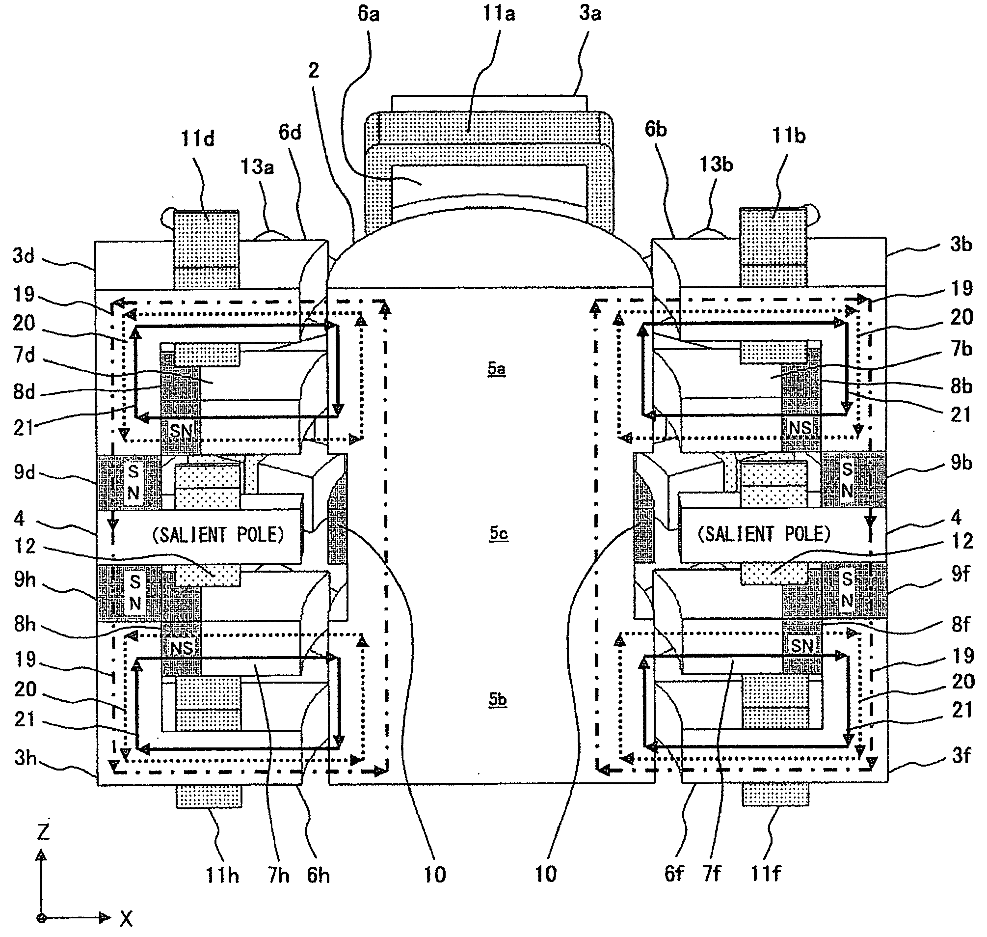
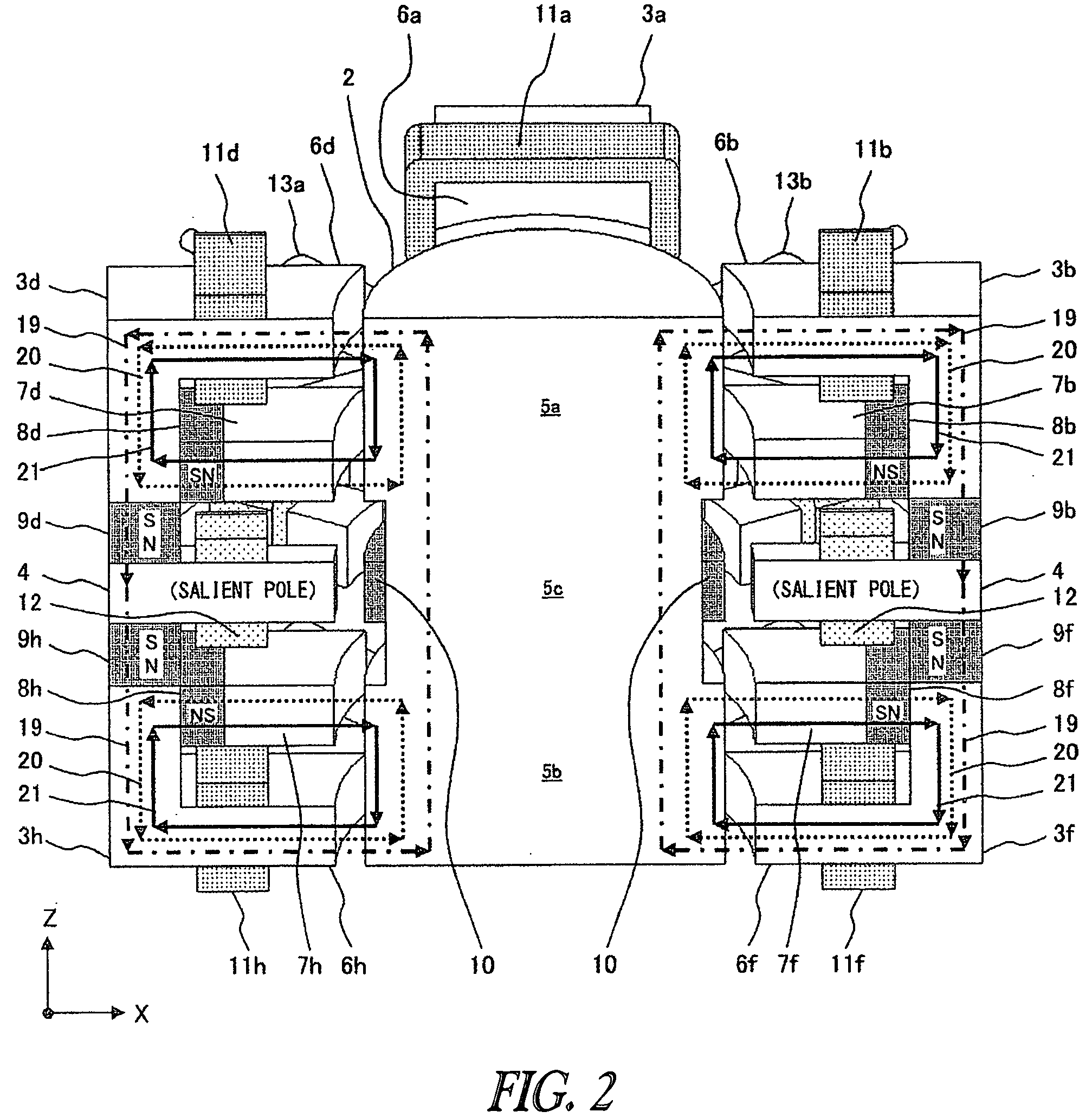
[0051]As configuration example 1, FIG. 2 shows a configuration in which the polarities on the rotor's side in the first permanent magnets 8 (8a through 8d) and the polarities on the rotor's side in the first permanent magnets 8 (8e through 8h) are opposite. This figure is a perspective-cross-sectional view along the line A-A′ of the direction of the flux line.

[0052]The second salient poles 7 are arranged on the side of the motor yoke 4, and the first salient poles 6 are arranged on the side of the ends of the rotor 2. However, the first salient poles 6 can be arranged on the side of the motor yoke 4, and the second salient poles 7 can be arranged on the side of the ends of the rotor 2.

[0053]As shown in FIG. 2, each of the bias magnetic fluxes 20 of the first permanent magnets 8 forms a magnetic path “-first permanent magnet 8-second salient pole 7-rotor yoke 5-first salient pole 6-”. Each of the magnetic fluxes 19 of the second permanent magnets 9 forms a magnetic...

configuration example 2

OF MAGNETIC BEARING

[0061]As configuration example 2, FIG. 3 shows a configuration in which the polarities on the rotor's side in the first permanent, magnets 8 (8a through 8d) and the polarities on the rotor's side in the first permanent magnets 8 (8e through 8h) are the same. This figure is a perspective-cross-sectional view along the line A-A′ of the direction of the flux line.

[0062]In configuration 2, the polarity on the rotor's side in the first permanent magnets 8 and the polarity on the motor yoke 4 side in the second permanent magnets 9 are both north pole. However, the polarity on the rotor's side in the first permanent magnets 8 and the polarity on the motor yoke 4 side in the second permanent magnets 9 may both be the south pole.

[0063]The second salient poles 7 are arranged on the side of the motor yoke 4 and the first salient poles 6 are arranged on sides of both ends of the rotor 2; however, the first salient poles 6 may be arranged on the side of the motor yoke 4, and t...

example 1

VARIATION EXAMPLE 1

[0085]FIG. 6 shows a first variation example for the above example 1. The leakage of the magnetic flux from magnetic circuits that are not in the gaps between the magnetic bearing unit and the rotor 2 is taken into consideration, and the configuration is changed as described below in order to increase the performance of the magnetic suspension.

[0086]Each of the first permanent magnets 8 is divided, and permanent magnets are arranged on the surfaces facing the rotor 2 in the respective first salient poles 6 (6a through 6h) and the second salient poles 7 (7a through 7h) and at the roots of the second salient poles 7 (7a through 7h). In FIG. 6, the first permanent magnets 8 (8i through 8p) are arranged on the first salient poles 6 (6a through 6h). Also, the first permanent magnets 8 (8a through 8h and 8q through 8x) are arranged on the second salient poles 7 (7a through 7h).

[0087]The plurality of the first permanent magnets 8 may be arranged at any position on the sa...


PUM


Abstract

A magnetic levitation motor including a stator having magnetic bearing units and a motor unit, and a rotor provided to the stator. And the occurrence of an eddy current at a magnetic bearing is suppressed and the rotation loss of the rotor can be reduced, and also to provide a pump using such the magnetic levitation motor.

Description

TECHNICAL FIELD[0001]The present invention relates to a structure of a magnetic levitation motor and control thereof, and especially to a technique of a hybrid magnetic levitation motor of the double-bias permanent magnet type.BACKGROUND ART[0002]In recent years, hybridmagnetic levitation motors of the double-bias permanent magnet type have been proposed as magnetic levitation motors.[0003]The five-axis control type hybridmagnetic bearing disclosed in Patent Document 1 is intended to magnetically levitate the major axis rotor and to rotate it highly efficiently under five-axis control by using a bias magnetic flux generation permanent magnet. The magnetic paths are changed so that a magnetic suspension force greater than that of a magnetic levitation system that only uses an electromagnet is generated.[0004]According to Patent Document 2, double-bias type magnetic bearing (suspension control) succeeds in generating a greater magnetic suspension force by using a plurality of bias mag...

Claims


Application Information

Patent Timeline
Patent Type & Authority Applications(United States)
IPC IPC(8): H02K7/09
CPCF04D29/058F16C32/0459F16C32/044H02K11/0015H02K21/14H02K7/09H02K11/21F16C32/0487F16C2360/44F16C32/048F16C32/0465H02K21/00
Inventor ONUMA, HIROYUKI
Owner IWAKI
Why Eureka
Try Eureka