
Tapered roller bearing an automotive pinion shaft supporting apparatus utilizing same tapered roller bearing

Active Publication Date: 2007-06-07
JTEKT CORP
View PDF3 Cites 3 Cited by
  • Summary
  • Abstract
  • Description
  • Claims
  • Application Information

AI Technical Summary

Benefits of technology

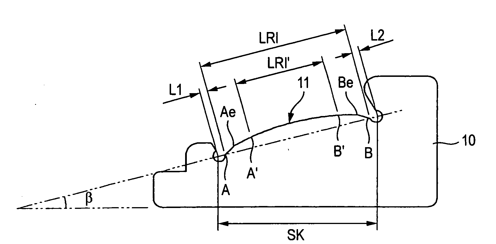
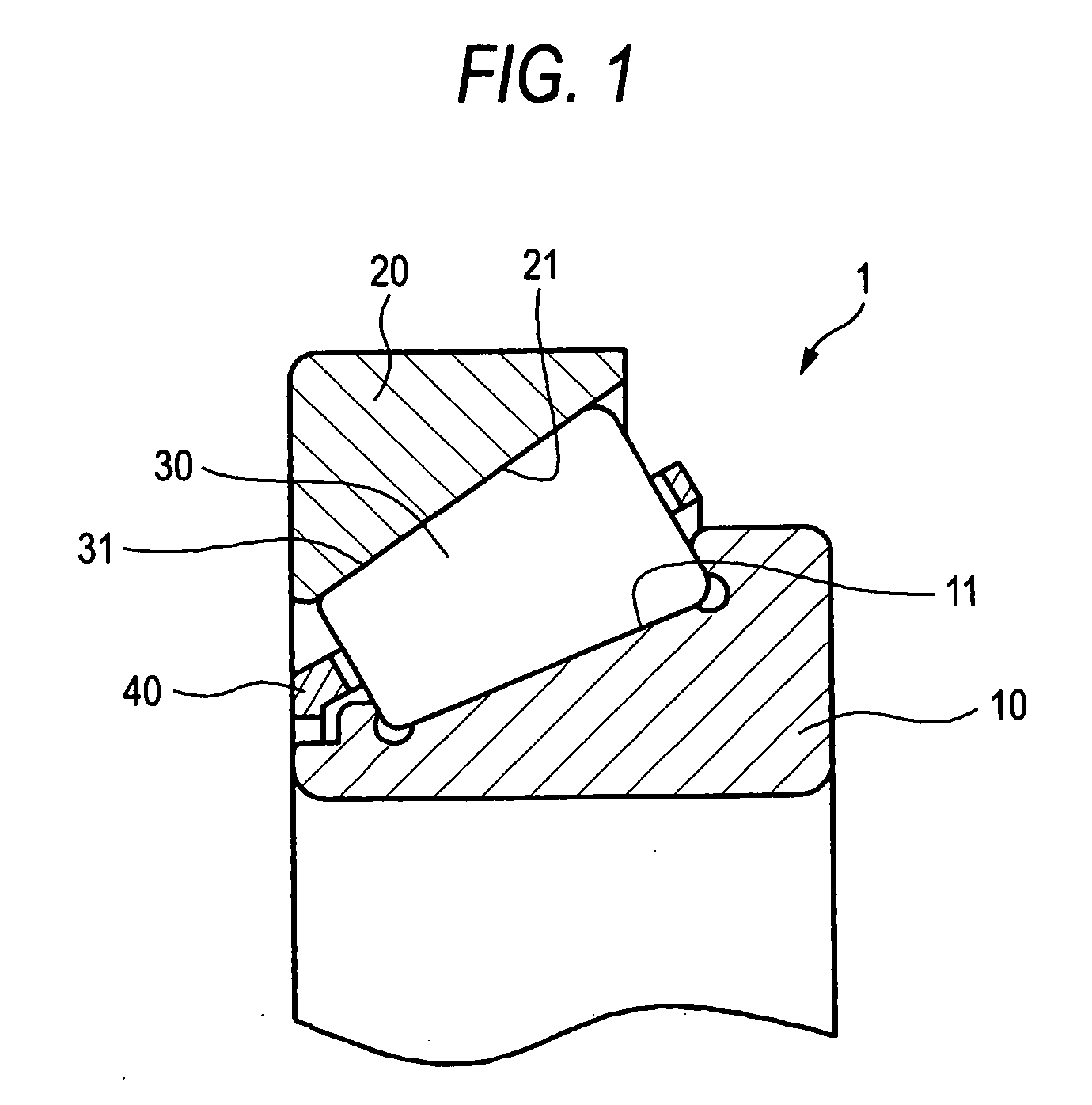
[0010] The invention is made in view of the situations, an object there of is to provide a tapered roller bearing which can reduce running torque by specifying, as quantity, crowning applied to rolling contact surfaces of tapered rollers and raceway surfaces of inner and outer rings and suppress the reduction in bearing life even in the case that the contact pressure of the contact surface between the rolling contact surface and the raceway surfaces, and an automotive pinion shaft supporting apparatus which utilizes the tapered roller bearing so provided.

Problems solved by technology

However, there had been no attempt to grasp the crown as quantity so as to specify the crowning amount so imparted to thereby reduce the running torque of the tapered roller bearing.
Therefore, the generation of abrasion of the contact surface and surface flaking become significant, thereby the life of the tapered roller bearing may be shorten.
Due to this, there is a case that the main dimensions of the tapered roller bearing have to be relatively large in order to decrease the contact pressure, which leads a problem that further lowering torque and further downscaling are inhibited.
Especially, if the contact pressure between the rolling contact surface and the raceway surfaces is high, the generation of the surface flaking of the contact surface is accelerated due to the foreign matters such as abrasive powder of the gear being interposed between the rolling contact surface and the raceway surfaces, thereby a reduction in life of the tapered roller bearing becomes significant.

Method used


Image

  • Tapered roller bearing an automotive pinion shaft supporting apparatus utilizing same tapered roller bearing
  • Tapered roller bearing an automotive pinion shaft supporting apparatus utilizing same tapered roller bearing
  • Tapered roller bearing an automotive pinion shaft supporting apparatus utilizing same tapered roller bearing

Examples


example

[0115] Next, the results of a comparison investigation will be described which was carried out on an example of the invention and comparison examples (1, 2) in which specific values were set accordingly. Hereinafter, methods of manufacturing the example of the invention and the comparison examples will be described.

[0116] The example of the invention was manufactured in the following manner. A material prepared to SAE5120 was used, and inner and outer ring materials were formed by working the SAE5120 material, the inner and outer ring materials being given a heat treatment under the following conditions. Namely, an ordinary carburizing and quenching treatment, a pre-tempering treatment, a sub-zero treatment and a proper tempering treatment were given in this order. The ordinary carburizing and quenching treatment was given such that the materials were held at 930° C. for 5 hours for carburizing, and thereafter the materials were cooled down to a quenching temperature of 850° C. and...


PUM

PropertyMeasurementUnit
Lengthaaaaaaaaaa
Fractionaaaaaaaaaa
Fractionaaaaaaaaaa

Abstract

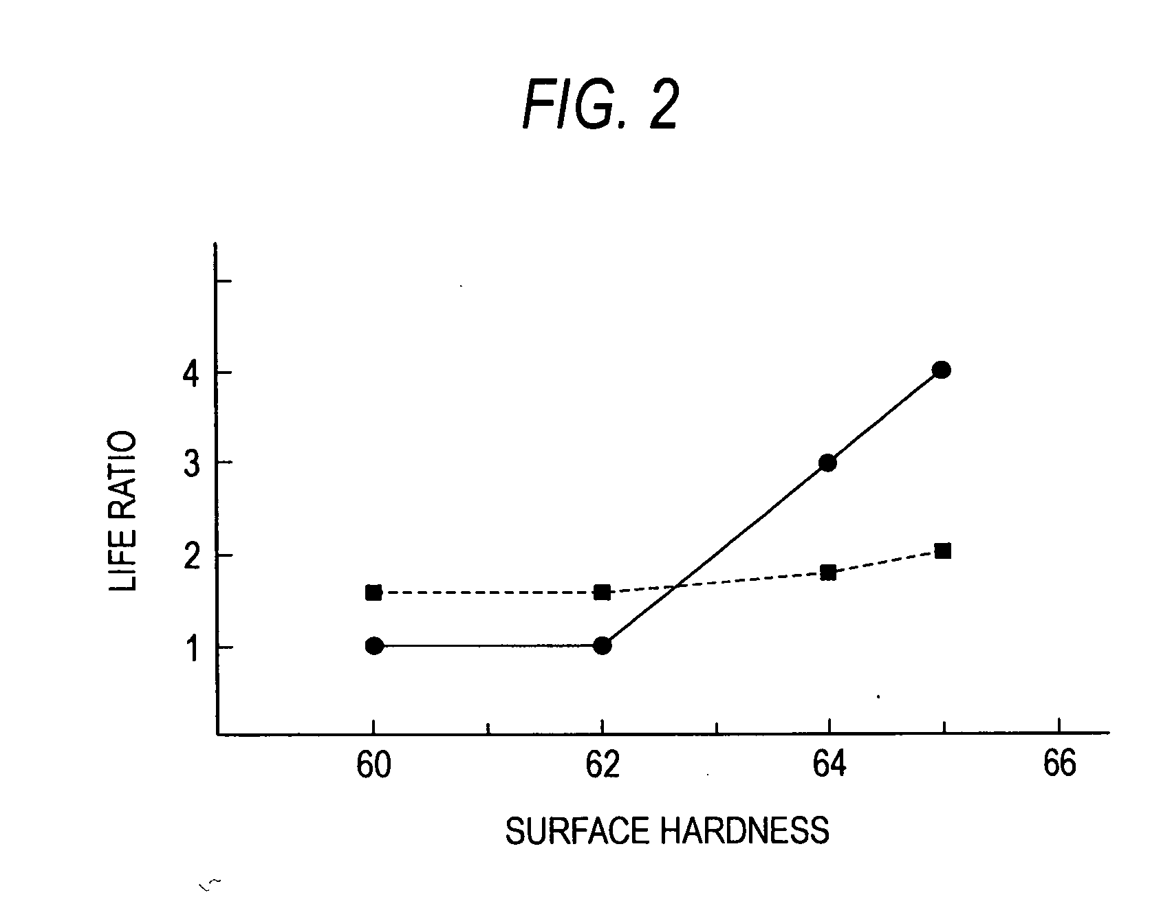
A tapered roller bearing according to the invention is such that the surface hardnesses of a raceway surface of an inner ring and rolling contact surfaces of tapered rollers are set to 63 to 69HRC. In addition, respective raceway surfaces of an outer ring and the inner ring and the rolling contact surfaces of the tapered rollers are crowned and are set such that a total crowning amount is 50 μm or larger, an outer crowning rate is 40% or larger and a roller crowning rate is 20% or smaller.

Description

BACKGROUND OF THE INVENTION [0001] The present invention relates to a tapered roller bearing which is preferably used in an automotive pinion shaft supporting apparatus as in a differential and a transaxle and in a transmission of a vehicle or the like, and an automotive pinion shaft supporting apparatus which uses the tapered roller bearing. [0002] In recent years, there has been increasing a demand for improvement in fuel economy of motor vehicles, and in association with the demand, there is expressed a desire to reduce the running torque of tapered roller bearings which are used to support rotational shafts of transmissions and differentials installed on those motor vehicles. [0003] In these situations, as a method of reducing the running torque of a tapered roller bearing, there is a method of reducing the rolling friction of a tapered roller bearing by crowning rolling contact surfaces of tapered rollers and raceway surfaces of inner and outer rings. [0004] As the method like ...

Claims


Application Information

Patent Timeline
IPC IPC(8): F16C33/58F16H57/021F16H57/037
CPCC21D1/18C21D1/25C21D1/785C21D6/04C21D9/40C21D2211/001C21D2211/008F16C19/225F16C19/364F16C33/366F16C33/64F16C2240/50F16C23/088F16C2361/61
Inventor TODA, KAZUTOSHIKAWAGUCHI, KOUJIOHSHIMA, HIROYUKIMASUDA, NAOKIMATSUYAMA, HIROKI
Owner JTEKT CORP
Learn More