Leakage Detection Device of Vehicle Mounted Power Supply System
- Summary
- Abstract
- Description
- Claims
- Application Information
AI Technical Summary
Benefits of technology
Problems solved by technology
Method used
Image

Examples
first example
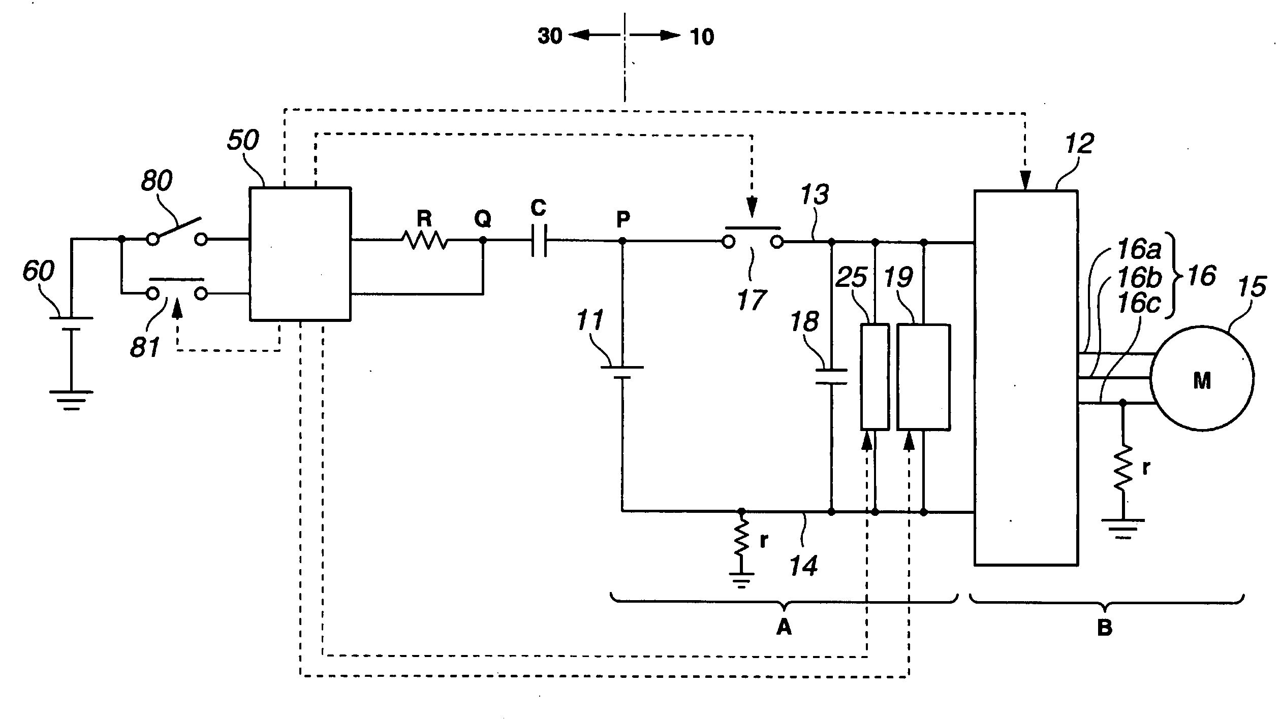
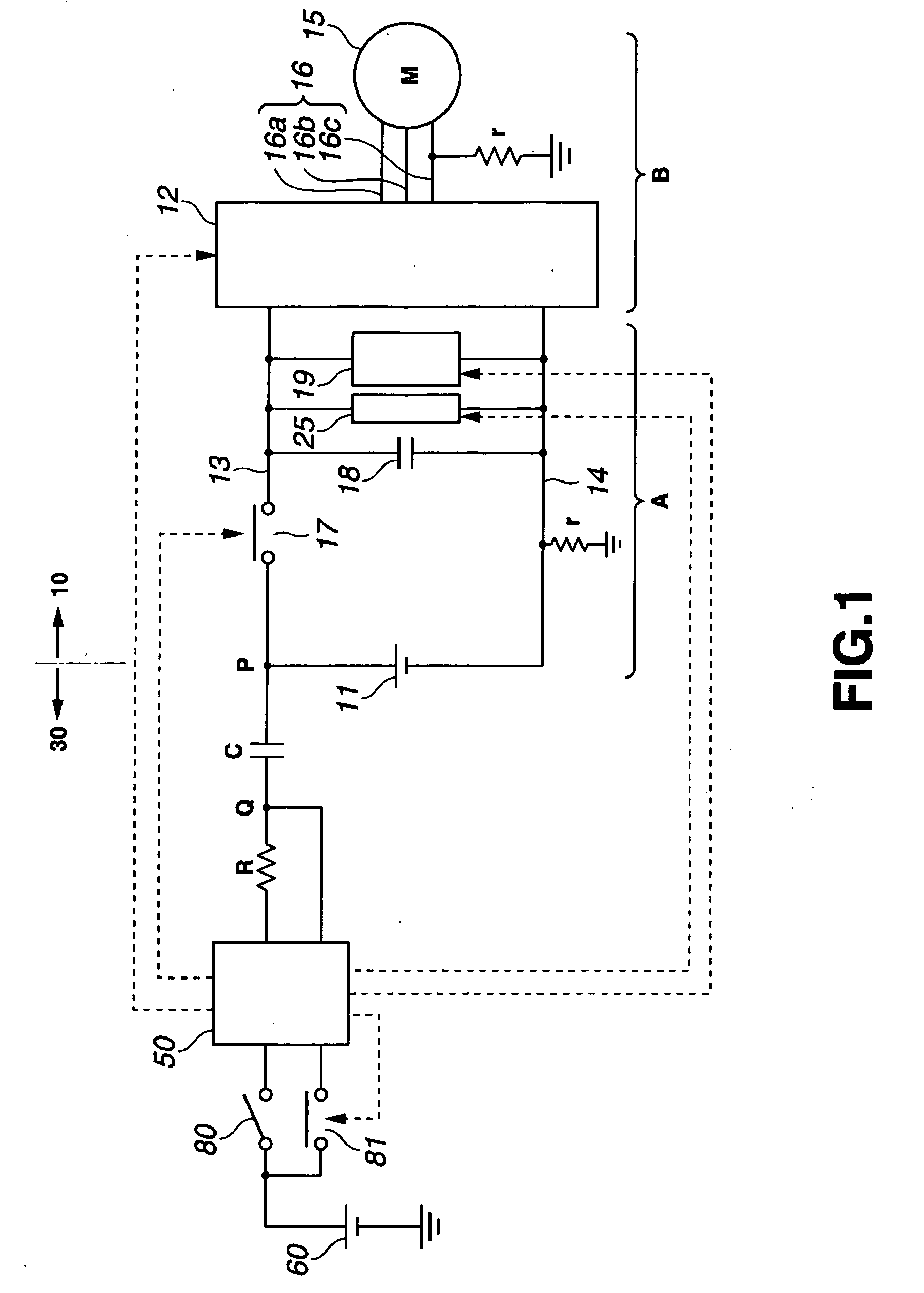
[0080]FIG. 1 is a diagram showing a configuration of First Example. In FIG. 1, the leakage detection device of the vehicle-mounted power supply system comprises a power supply system 10 and a leakage detection section 30.
[0081]The power supply system 10 shown in FIG. 1 is basically the same as the power supply system as described using FIG. 6, except that the contactor 17b is not provided on the negative line 14 in FIG. 1. In First Example, a contactor may be provided on the negative line 14. However, in doing so in the leakage detection device of First Example, it is necessary that any one of the contactors provided on the positive line and the negative line be turned on while the other is turned off.
[0082]The power supply system 10 comprises a DC high voltage circuit A and an AC high voltage circuit B. The DC high voltage circuit A comprises a battery 11 for the direct current; a positive line 13 and a negative line 14 that are connected respectively to a positive and a negative s...
second example
[0116]In Second Example, in response to operation for stopping the vehicle from working, it is detected whether or not the leakage exists.
[0117]FIG. 4 is a flow chart showing a procedure of leakage detection process in Second Example. The contactor 17 is turned on before the ignition key is turned off.
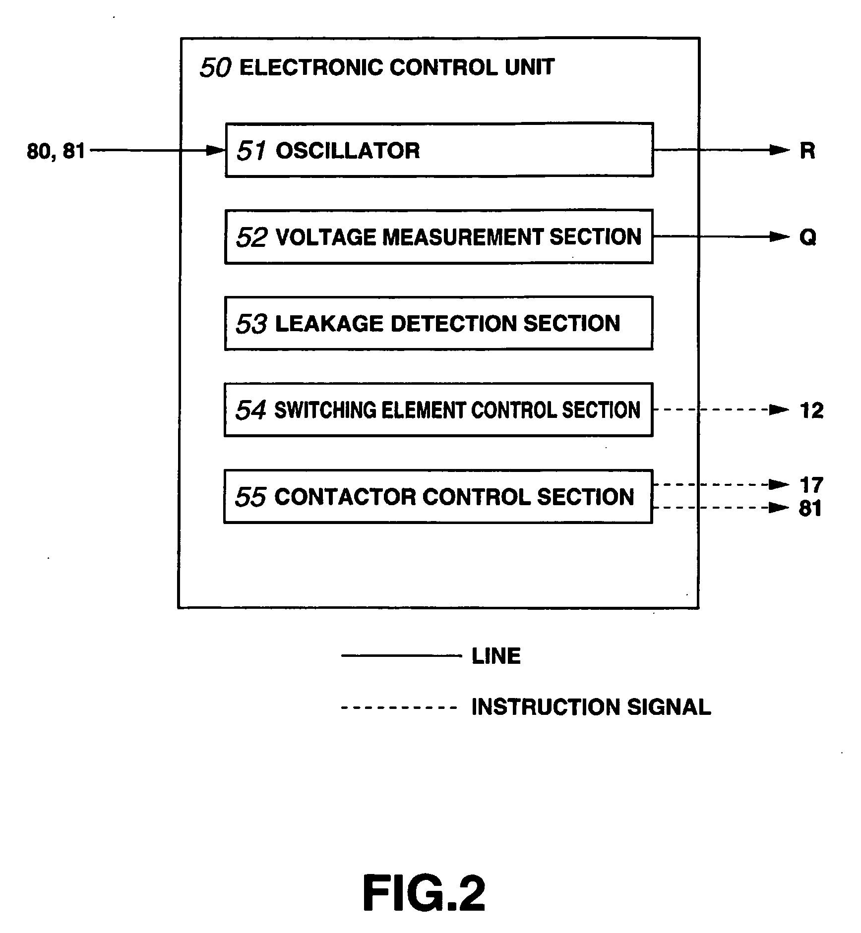
[0118]When the operator stops the vehicle from working by turning off the ignition key, the switch 80 is caused to be turned off while the contactor control section 55 in the electronic control unit 50 turns off the contactor 17 (step S50, step S51). Next, a process of decreasing the DC voltage at the capacitor 18 is implemented until the voltage Vd measured by the DC voltage measurement section 19 is decreased to less than the threshold value of 10V (step S52, step S53).
[0119]When the voltage Vd measured by the DC voltage measurement section 19 is less than the threshold value of 10V, the switching element control section 54 in the electronic control unit 50 turns off all the gates in...
third example
[0143]In First Example and Second Example, it is assumed that the leakage is detected at the time of activating the vehicle or of stopping the vehicle from working. Third Example will be described by assuming a case where the leakage detection is performed while the vehicle is being in operation.
[0144]FIG. 5 is a flow chart showing a process procedure of Third Example.
[0145]During the normal control, for example, switching signal in accordance with the operation of the operation lever is applied to each of the IGBT elements (switching elements) 76 in the IGBT inverter circuit 12, and the AC motor 15 is driven in accordance with the operation of the operation lever (normal control).
[0146]When a signal for instructing the detection of the leakage is inputted, the switching signal for causing the AC motor 15 to be in a stopped status is automatically applied to each of the IGBT elements (switching elements) 76 regardless of the operation status of the operation lever. Additionally, it ...
PUM
 Abstract
Description
Claims
Application Information
 - R&D
- Intellectual Property
- Life Sciences
- Materials
- Tech Scout
- Unparalleled Data Quality
- Higher Quality Content
- 60% Fewer Hallucinations
Browse by: Latest US Patents, China's latest patents, Technical Efficacy Thesaurus, Application Domain, Technology Topic, Popular Technical Reports.
© 2025 PatSnap. All rights reserved.Legal|Privacy policy|Modern Slavery Act Transparency Statement|Sitemap|About US| Contact US: help@patsnap.com