Novel free layer design for TMR/CPP device

a technology of tmr/cpp and free layer design, applied in the direction of measurement devices, magnetic measurements, instruments, etc., can solve the problems of change in the resistance of the layered configuration, excessive magnetostriction of the cofeb layer, etc., to reduce the yield loss related to instability, eliminate hysteresis and non-linearity

Inactive Publication Date: 2009-05-14
HEADWAY TECH INC
View PDF5 Cites 18 Cited by
  • Summary
  • Abstract
  • Description
  • Claims
  • Application Information

AI Technical Summary

Benefits of technology

[0021]A fourth object of this invention is to provide such a free layer structure wherein hysteresis and non-linearity in one of the component ferromagnetic layers is reduced.
[0023]It is asserted that the free layer formed in this way will be improved in TMR by between 5% and 10%, while retaining such other advantageous properties of a free layer as usable areal resistance (RA). In addition, if a layer of NiFe with very negative magnetostriction is used, then, after lapping of the ABS, the magnetization of the NiFe will be aligned parallel to the ABS the resulting coupling field of the structure will act as a uniformly distributed biasing field for the CoFeB layer by the magnetic coupling across the non-magnetic layer. This will help in eliminating hysteresis and non-linearity in the magnetic switching of the CoFeB free layer and, thereby, reduce yield losses related to instability.

Problems solved by technology

This polarization, in turn, affects their scattering properties within the layers and, consequently, results in changes in the resistance of the layered configuration.
The CoFeB layer, however, exhibits excessive magnetostriction.

Method used


Image

  • Novel free layer design for TMR/CPP device
  • Novel free layer design for TMR/CPP device
  • Novel free layer design for TMR/CPP device

Examples


Embodiment Construction

[0029]The preferred embodiment of the present invention is a TMR or CPP GMR sensor structure of good areal resistance, good free layer coercivity, improved magnetoresistive ratio (dRJR), adjustable magnetostriction and improved stability and hysteresis control resulting from in-stack biasing. This improvement is obtained by the introduction of a tri-layer (or four-layer) free layer comprising a CoFeB layer and an NiFe layer between which is interposed a thin layer of a non-magnetic material, such as Hf, V, Zr, Nb, Ta, Mo, or Cr, that is formed to a thickness between approximately 0 and 15 angstroms.

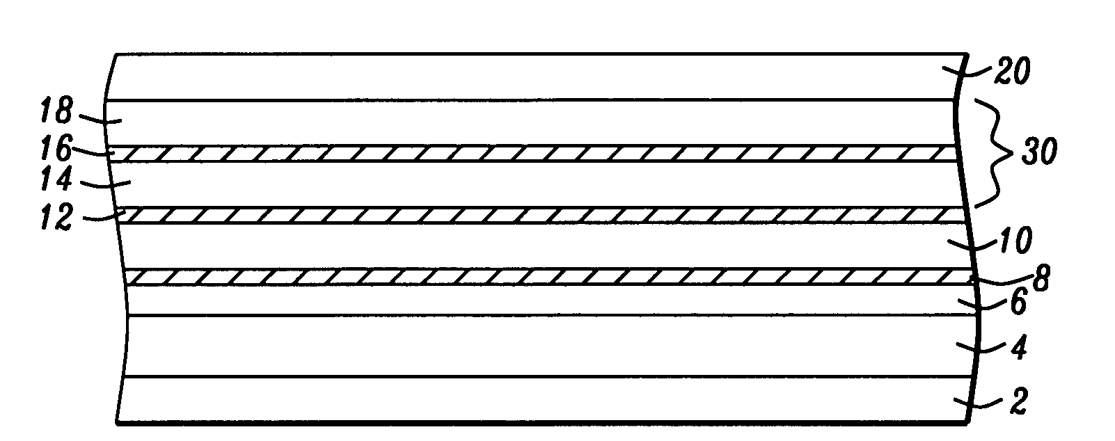
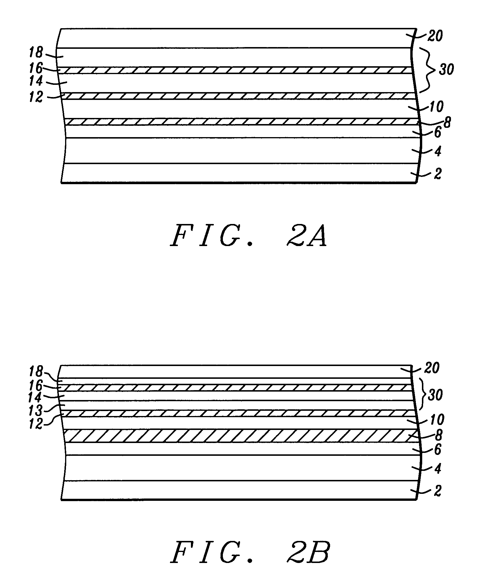
[0030]Referring to FIG. 2A, there is shown schematically a TMR stack of the general form into which the tri-layered free layer of the present invention can be introduced so as to meet the objects of the invention. In the figure there is seen a seed layer (2) an antiferromagnetic pinning layer (4), a tri-layered pinned layer that comprises an outer pinned layer (6) a Ru coupling layer (8) ...


PUM


Abstract

A TMR sensor and a CPP GMR sensor all include a free layer that is of the form CoFexBy / non-magnetic layer / NiFez or of the form CoFe / CoFeB / non-magnetic layer / NiFe, where, in one embodiment, the thickness of the non-magnetic layer is less than approximately 15 angstroms and the atom percentage x, z of Fe can vary between 0 and 70% for x and 0 and 100% for z and the atom percentage, y, of B can vary between 0 and 30%. This arrangement can produce a 5-10% improvement in dR / R and can allow the coupling field between the CoFeB and the NiFe to be strong enough that an in-stack biasing of the CoFeB layer occurs and the hysteresis behavior and stability of the sensor is improved.

Description

RELATED PATENT APPLICATION[0001]This patent application is related to Docket Number HMG 06-040, Ser. No. ______, Filing Date ______, assigned to the same assignee as the present invention and which is incorporated by reference herein in its entirety.BACKGROUND OF THE INVENTION[0002]1. Field of the Invention[0003]This invention relates generally to magnetoresistive read sensors and particularly to the free layer formations of such sensors operating in a tunneling magnetoresistive (TMR) configuration and current-perpendicular-to- plane (CPP) GMR configurations.[0004]2. Description of the Related Art[0005]In simplest form, the usual giant magnetoresistive (GMR) read sensor consists of two magnetic layers, formed vertically above each other in a parallel planar configuration and separated by a conducting, but non-magnetic, spacer layer. Each magnetic layer is given a unidirectional magnetic moment within its plane and the relative orientations of the two planar magnetic moments determin...

Claims


Application Information

Patent Timeline
Patent Type & Authority Applications(United States)
IPC IPC(8): G01R33/09G01R3/00H01L21/00
CPCG01R33/09
Inventor WANG, HUI-CHUANZHAO, TONGZHANG, KUNLIANGLI, MIN
Owner HEADWAY TECH INC
Why Eureka
Try Eureka