Core and method for producing core

a technology of winding wire and core, which is applied in the direction of magnetic core, transformer/inductance details, magnetic circuits characterised by magnetic materials, etc., can solve the problems of increasing the amount of heat generated in the winding wire, affecting the downsizing of the motor, and the current density and heat generation density of the winding wire cannot be made high, so as to achieve high heat resistance

Inactive Publication Date: 2009-05-14
TOYOTA JIDOSHA KK
View PDF2 Cites 11 Cited by
  • Summary
  • Abstract
  • Description
  • Claims
  • Application Information

AI Technical Summary

Benefits of technology

[0017]According to the present invention, the core has the dust core as the base body, and the core having high heat resistance can be provided.

Problems solved by technology

However, because the core described in JP 2004-242443 A employs a resin film as the insulating film layer, the current density and heat-generation density of the winding wire can not be made high because a heat-resistant temperature is low (approximately 200° C. at the highest).
As such, the downsizing of the motor is impeded.
More specifically, although the demand for downsizing of motors used in automobiles has recently been increasing, when the winding wire density is increased and larger amounts of current is directed to it in connection with downsizing, the amount of heat generated in the winding wire increases.
In addition, because heat mass becomes small by downsizing, the motor temperature tends to increase.
Therefore, in connection with the downsizing of the motor, the height of the heat-resistant temperature becomes very significant, and if the heat resistance of the insulating film layer of the core described above is low, the downsizing is hindered.

Method used


Image

  • Core and method for producing core
  • Core and method for producing core
  • Core and method for producing core

Examples


Embodiment Construction

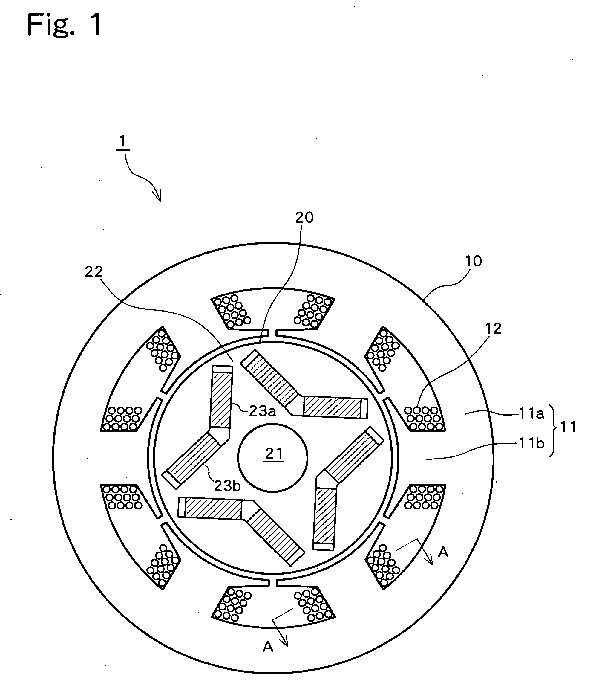
[0023]Embodiments of the present invention are described below with reference to the drawings. Although in the following an example of applying the core according to the present invention to the stator core of a so-called concentrated-wound permanent magnet embedded motor is described, this is only an explanatory example, and the core according to the present invention can also be applied to other types of motors.

[Overall Motor Structure]

[0024]FIG. 1 is a schematic sectional view of a motor 1 to which the core according to the present invention is applied. In FIG. 1, the motor 1 is configured from a combination of a concentrated-wound type stator 10 and a permanent magnet embedded type rotor 20.

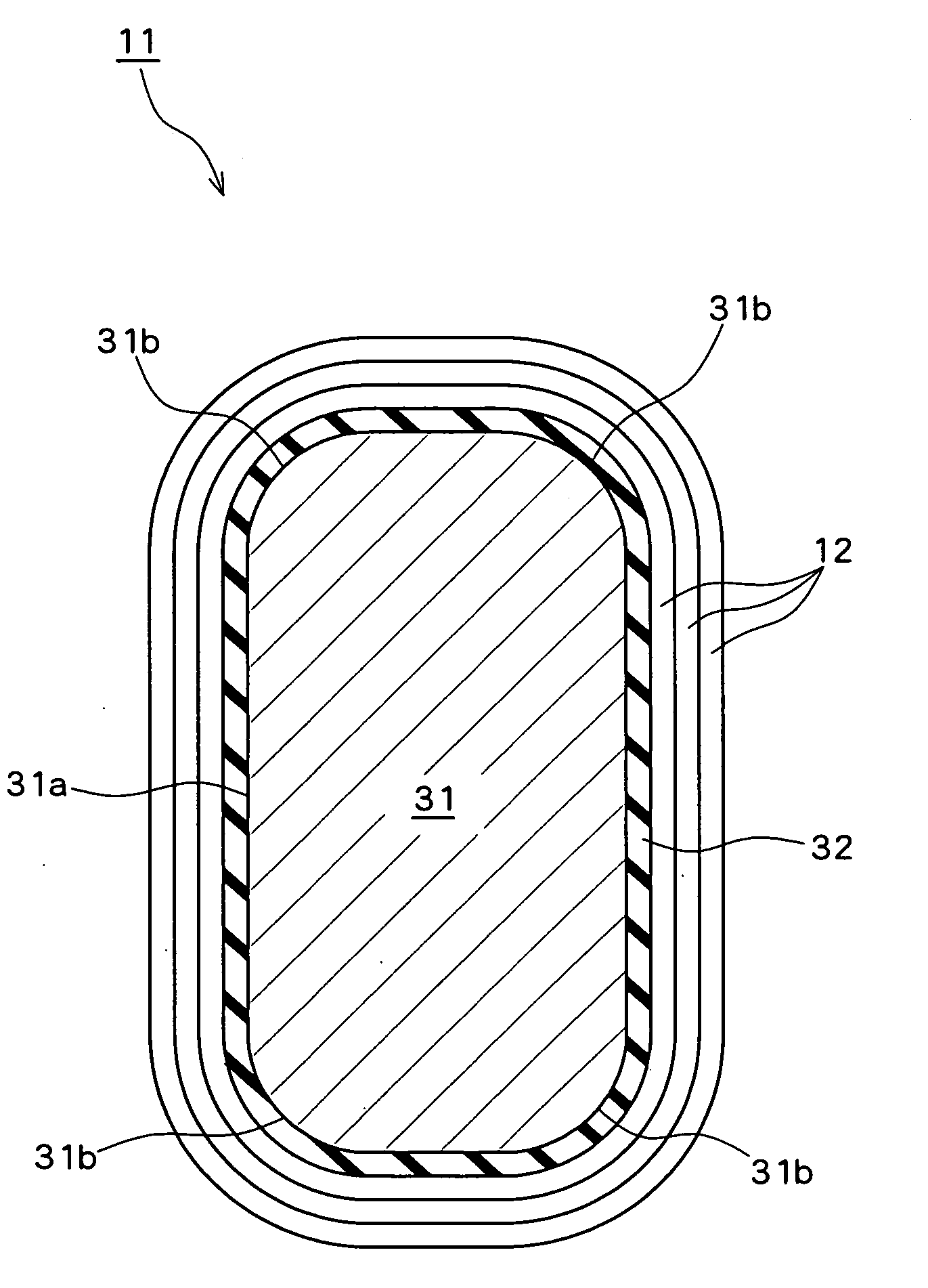
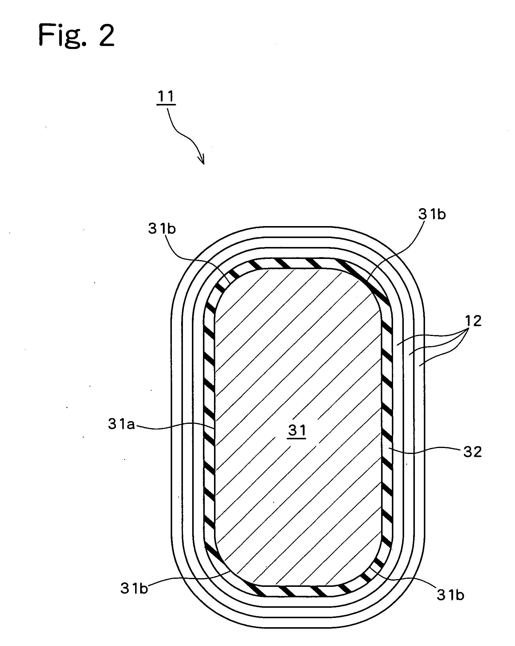
[0025]The stator 10 is substantially cylindrical and mainly comprised of a stator core 11 and a winding wire 12 which is wound around it. The stator core 11 is comprised of a substantially cylindrical yoke portion 11a and plural (six in this example) tooth portions 11b which are disposed to e...


PUM

PropertyMeasurementUnit
heat-resistant temperatureaaaaaaaaaa
heat-resistantaaaaaaaaaa
timeaaaaaaaaaa

Abstract

Disclosed is a highly heat-resistant core which has a dust core as a base body. A dust core obtained by press-molding magnetic powder particles particles each of which are covered with an insulating film is used as the base body. An inorganic heat-resistant insulating film is formed on at least a part of a surface of the dust core which faces a winding wire.

Description

TECHNICAL FIELD[0001]The present invention relates to a core on which a winding wire is wound, and a method for producing the core.BACKGROUND ART[0002]FIG. 5 is a schematic sectional view of a tooth 51 of a motor core 50 described in JP 2004-242443 A. In FIG. 5, the motor core 50 is a dust core which is formed by compression molding of magnetic powder particles having an insulating film. The tooth 51 is formed to have an outer peripheral surface with a smooth curved surface. A resin is coated on the outer peripheral surface of the tooth 51 to form an insulating film layer 52, and a winding wire 53 is wound on the insulating film layer 52 around the whole circumference of the tooth 51.[0003]With a motor core 50 having the above structure as described in JP 2004-242443 A, because the outer peripheral surface of the tooth 51 is formed to have a smooth curved surface, no one portion of the winding wire 53 is subjected to a particularly high surface pressure, and an insulating film cover...

Claims


Application Information

Patent Timeline
Patent Type & Authority Applications(United States)
IPC IPC(8): H01F27/255B22F7/08
CPCH02K1/02Y10T29/49009H02K15/022H02K1/04
Inventor TATEMATSU, KAZUTAKAMIZUTANI, RYOJIENDO, YASUHIRO
Owner TOYOTA JIDOSHA KK
Why Eureka
Try Eureka