Radar image display

a technology of image display and target identification, applied in the field ofradar processing methods and systems, can solve the problems of significant delay in image processing, large processing power required for digitization and/or conversion, and large workload on the cpu and associated memory of the workstation, so as to improve target representation and reduce noise in the return signal

Inactive Publication Date: 2009-05-14
CURTISS WRIGHT CONTROLS
View PDF3 Cites 28 Cited by
  • Summary
  • Abstract
  • Description
  • Claims
  • Application Information

AI Technical Summary

Benefits of technology

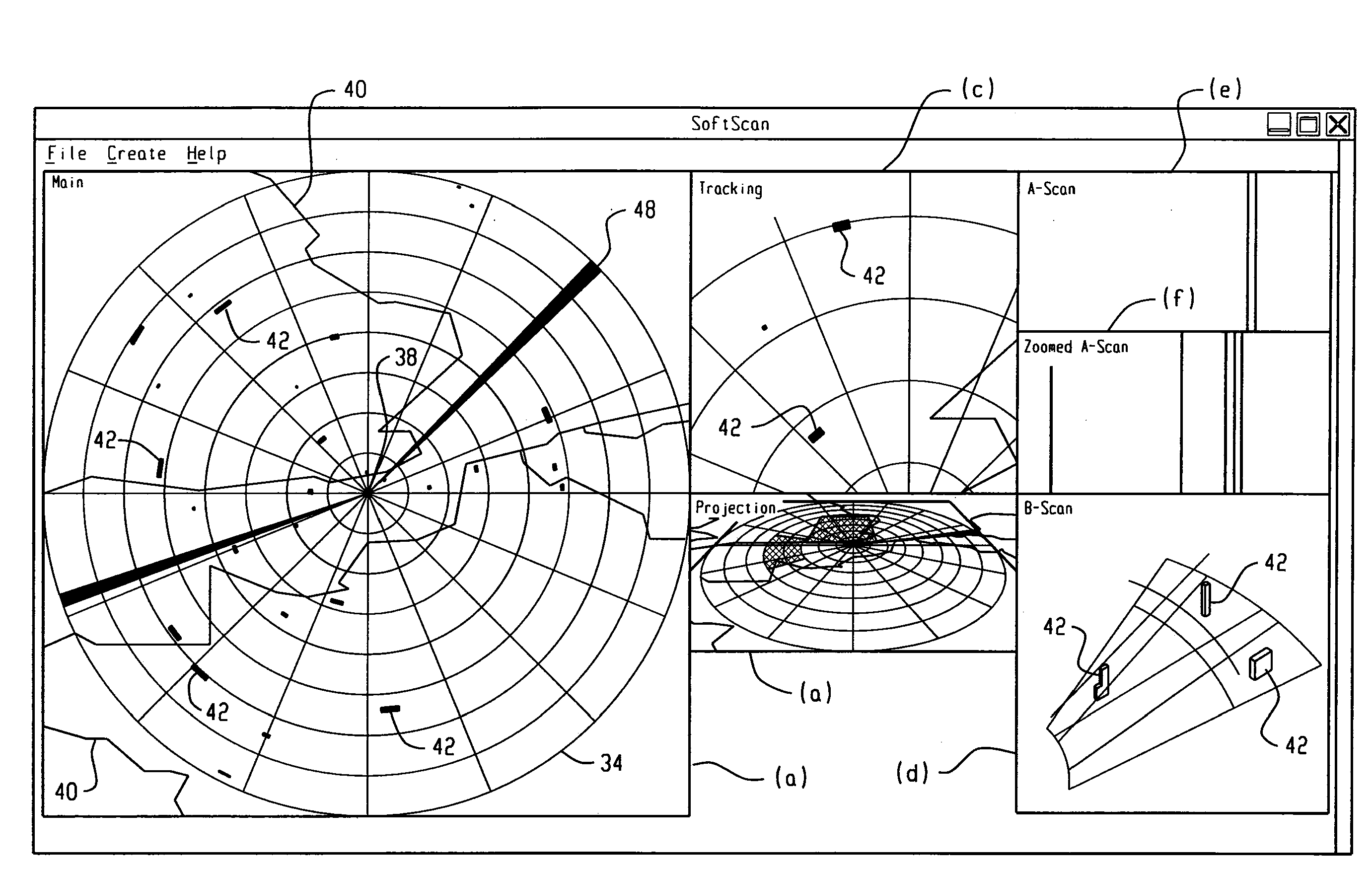
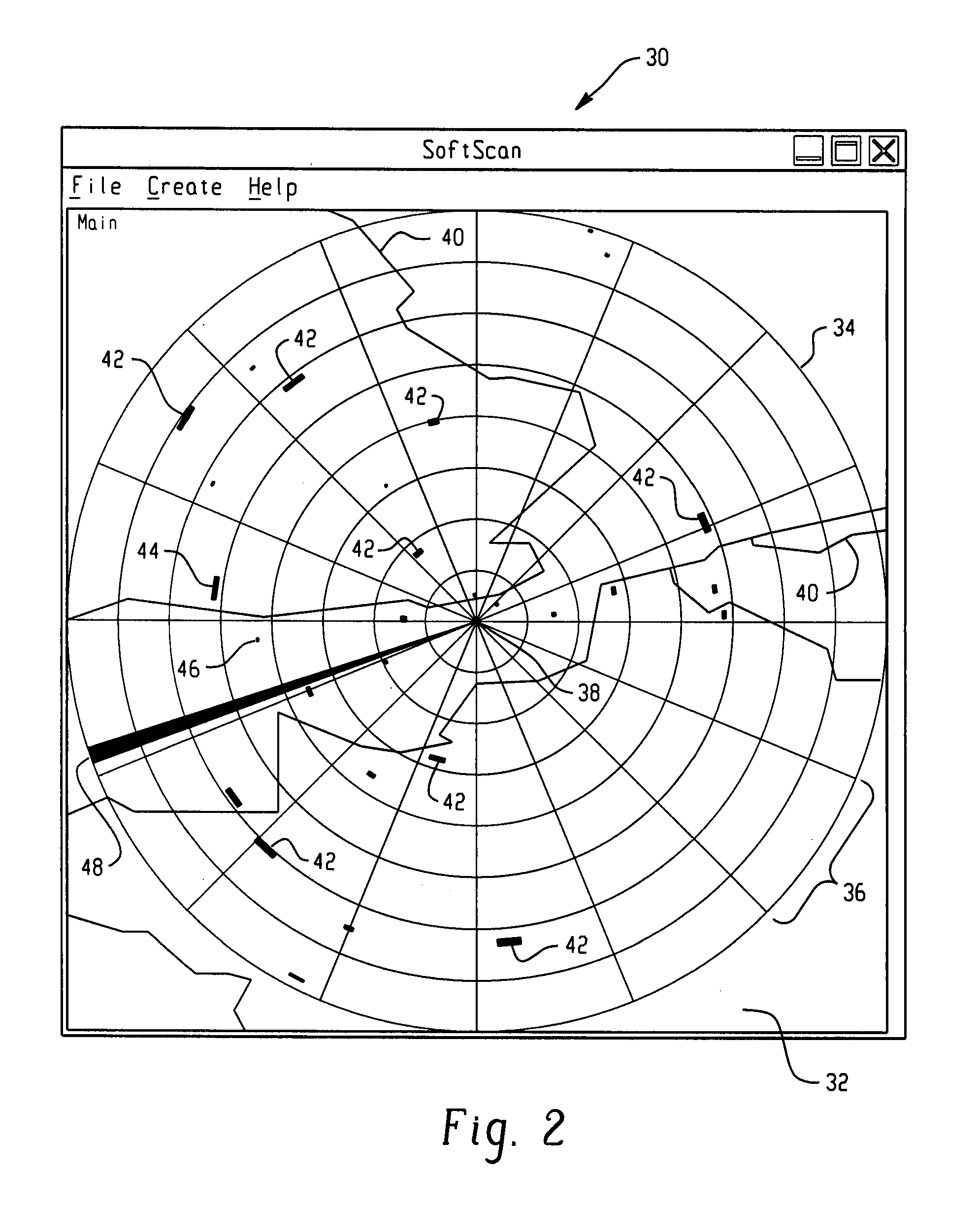
[0012]According to one aspect, the subject application involves a computer implemented method for improving the representation of targets within radar images, including the steps of receiving input data comprising at least one radar image; dividing the image into a plurality of radial components; and applying a filtering means to at least two adjacent radial components to thereby reduce noise in the return signals from any target present within those components.

Problems solved by technology

However, a potential drawback of many such implementations is that the amount of processing power required to perform the digitization and / or conversion is relatively high, which consequently places significant demands on the workstation's CPU and associated memory.
In some cases, the CPU demands may be so great that this introduces a significant delay into the image processing, such that the displayed image lags behind the radar signal feed, which is obviously undesirable within most radar applications.
However, in nearly all cases, such implementations have fallen significantly short of removing the processing burden from the CPU.
Therefore, to date, most of the known computer-based implementations of radar display systems are highly CPU intensive.
However, it is usually the case that existing techniques used to process the radar images generally do not make best use of the available data and, in particular, are not especially suited to mitigate against the effects of noise within the radar images.
Therefore, the representation of targets within a displayed image may not match those that are theoretically possible given the power and / or resolution of the radar display system.

Method used


Image

  • Radar image display
  • Radar image display
  • Radar image display

Examples


Embodiment Construction

[0072]Certain terminology is used herein for convenience only and is not to be taken as a limitation on the present invention. Relative language used herein is best understood with reference to the drawings, in which like numerals are used to identify like or similar items. Further, in the drawings, certain features may be shown in somewhat schematic form.

[0073]It is also to be noted that the phrase “at least one of”, if used herein, followed by a plurality of members herein means one of the members, or a combination of more than one of the members. For example, the phrase “at least one of a first widget and a second widget” means in the present application: the first widget, the second widget, or the first widget and the second widget. Likewise, “at least one of a first widget, a second widget and a third widget” means in the present application: the first widget, the second widget, the third widget, the first widget and the second widget, the first widget and the third widget, the...


PUM


Abstract

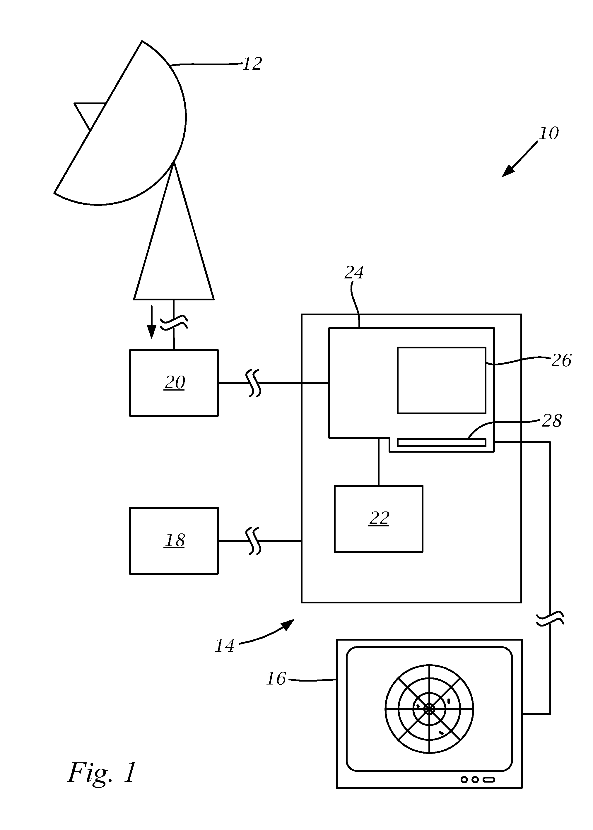
A method is provided that facilitates generating a radar image to be displayed by a radar system. The method includes receiving range data and azimuth data carried by a radar signal transmitted from a radar antenna in communication with the radar system, wherein the range data and the azimuth data represent the radar image as a plurality of azimuth segments that collectively form the radar image in a polar coordinate system. The range data and the azimuth data are translated into abscissa data and ordinate data that represent the radar image in a Cartesian coordinate system, and noise is filtered from the radar image, followed by generation of the radar image including the target to be displayed by a display screen to an operator.

Description

CROSS-REFERENCE TO RELATED APPLICATIONS[0001]This application claims the benefit of U.K. Patent Application No. GB0719880.7, filed Oct. 12, 2007, the entirety of which is incorporated herein by reference.BACKGROUND OF THE INVENTION[0002]1. Field of the Invention[0003]This application relates generally to an improved radar processing method and system, and more specifically to radar imaging and target identification, and in particular to a method and apparatus for improving the representation of targets within radar images.[0004]2. Description of Related Art[0005]Radar is the primary airspace sensor for ground-based, marine and airborne surveillance and monitoring applications. Its use within both commercial and military environments is widely known, and to date it remains the most effective technique for identifying targets within an area of interest.[0006]Conventional radar display systems have historically been based on cylindrical cathode ray tube (CRT) arrangements, in which a p...

Claims


Application Information

Patent Timeline
Patent Type & Authority Applications(United States)
IPC IPC(8): G01S13/00
CPCG01S7/298
Inventor MAINDS, MICHAEL GARETHGASCOYNE-CECIL, ANDREW
Owner CURTISS WRIGHT CONTROLS
Why Eureka
Try Eureka