
System for determining position over a network

a network and position determination technology, applied in direction finders, instruments, measurement devices, etc., can solve problems such as system failure and carrier cycle ambiguity, and achieve the effect of accurately determining position

Active Publication Date: 2009-05-14
NOVATEL INC
View PDF28 Cites 36 Cited by
  • Summary
  • Abstract
  • Description
  • Claims
  • Application Information

AI Technical Summary

Benefits of technology

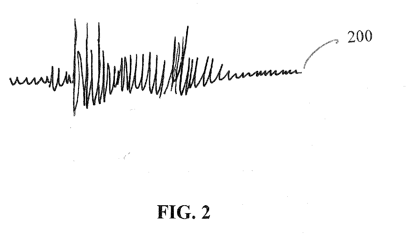
[0007]A method and system for providing position information uses existing radiated signals of opportunity, such as AM or FM radio signals, television signals, signals from geo-stationary communications satellites, and so forth, and, more particularly, the modulation of the signals of opportunity. The method and system use the essentially pseudorandom properties of the modulated signals to establish times of arrival of the signals of opportunity without ambiguity. Using the signals from a plurality of signal of opportunity transmitters, the remote receivers can accurately determine their positions.

Problems solved by technology

The obstacle that the Counselman system must overcome for precise position, however, is the carrier cycle ambiguity.

Method used


Image

  • System for determining position over a network
  • System for determining position over a network
  • System for determining position over a network

Examples


Embodiment Construction

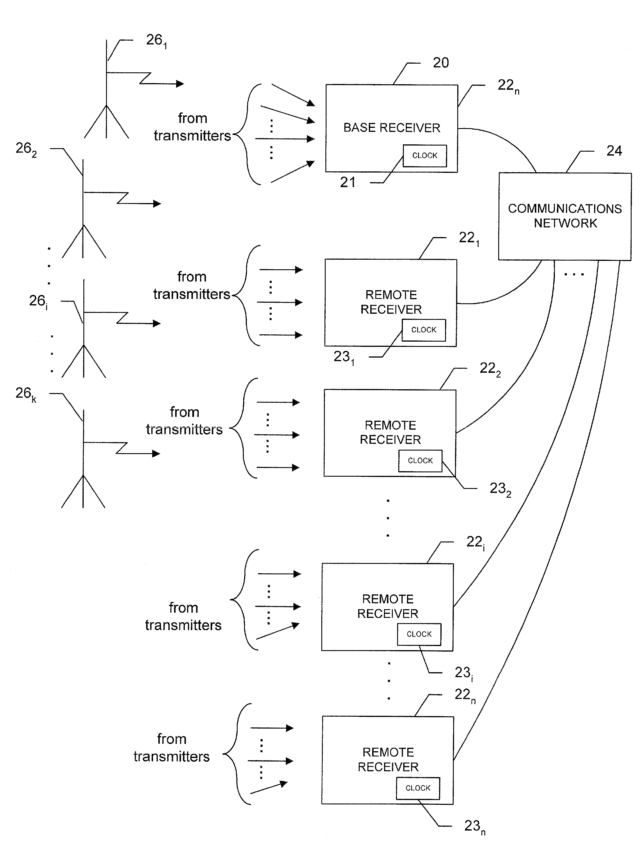
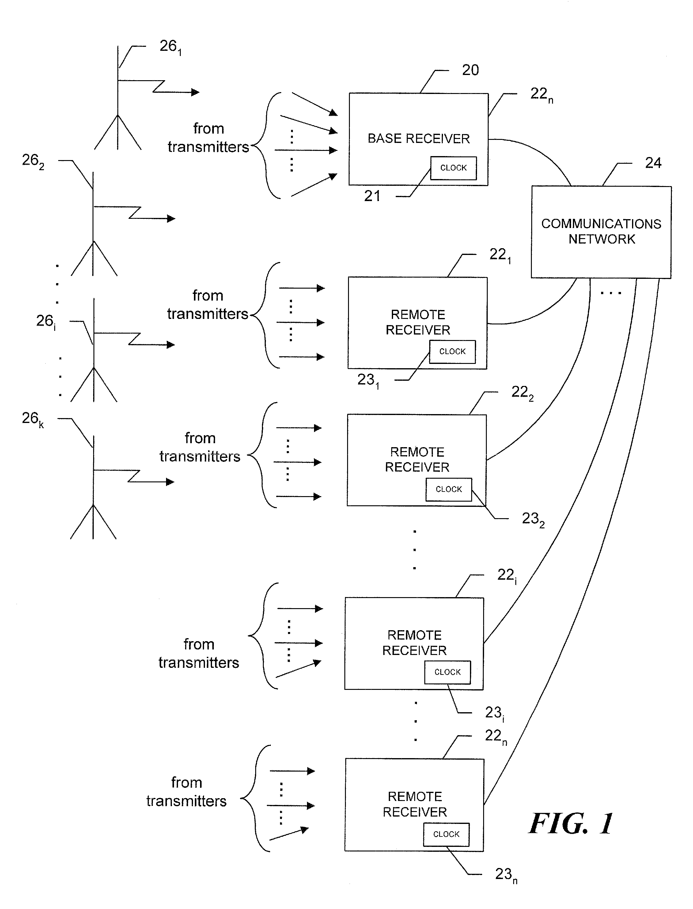
[0017]Referring to FIG. 1, a reference, or base station, receiver 20 (referred to hereinafter as the “base receiver”) and remote receivers 221, 222 . . . 22n, are connected to a communication network 24, such as, for example, the internet or a private network. Each of the receivers receives signals broadcast from a plurality of high power radiators 261, 262 . . . 26j, with known locations, i.e., AM / FM radio transmitters, Beacon transmitters, television station transmitters, geo-stationary communications satellites, and so forth, with respective service areas that cover all or part of the network.

[0018]The broadcast signals, which are selected due to their quality of signal, known transmission locations, and continuous broadcast, are “signals of opportunity,” that is, signals that are broadcast at various frequencies and for purposes such as the transmission of random conversation or dialog. These are pre-existing signals, which are not specifically designed and operated for determin...


PUM


Abstract

A system to determine position, frequency and clock offsets over a network utilizing signals of opportunity transmitted by one or more transmitters with known locations, the system includes a base receiver with a clock and a known position that determines ranges to the transmitters, takes a series of samples of the signals of opportunity and time tags the series with times of receipt, calculated times of transmission based on the calculated ranges, or both. The base receiver transmits the time tagged series and, as appropriate, computed ranges to the remote receivers. A given remote receiver saves and time tags samples of the signals of opportunity, correlates the time-tagged series with the saved samples, and calculates a time offset as a time difference of the times of receipt at the remote receiver and either the time of receipt at the base receiver or the time of transmission calculated at the base receiver. The remote receiver calculates position based on the time offsets, and as appropriate, the ranges provided by the base receiver. The elevations of the remote receivers may be calculated as part of the position calculations, determined iteratively based on constraining the Z coordinate to an average elevation, or determined from differences in air pressure sensor readings at the base and remoter receivers.

Description

CROSS REFERENCE TO RELATED APPLICATIONS[0001]This application claims priority from U.S. Provisional Patent Application Ser. No. 60 / 987,523 filed Nov. 13, 2007; U.S. Provisional Patent Application Ser. No. 61 / 016,182 filed Dec. 21, 2007 and U.S. patent application Ser. No. 12 / 263,940 filed Nov. 3, 2008, which are assigned to a common Assignee and incorporated herein by reference in their entireties.BACKGROUND OF THE INVENTION[0002]1. Field of the Invention[0003]The invention relates generally to systems and methods for determining position and clock offsets using radiated “signals of opportunity,” such as radio and television signals.[0004]2. Background Information[0005]Determining position is critical for high speed wireless networks that provide hand-offs to the nearest cell tower or other network devices. Further, position is critical for accurate time transfer over the network. GNSS receivers can provide position information, as long as the antennas at the remote locations have s...

Claims


Application Information

Patent Timeline
IPC IPC(8): G01S5/10
CPCG01S5/0045G01S5/145G01S5/10G01S5/0236
Inventor LADD, JONATHANFENTON, PATRICK C.
Owner NOVATEL INC
Learn More